Abstract
We propose theoretically and verify experimentally a method of combining a q-plate and a spiral phase plate to generate arbitrary vector vortex beams on a hybrid-order Poincaré sphere. We demonstrate that a vector vortex beam can be decomposed into a vector beam and a vortex, whereby the generation can be realized by sequentially using a q-plate and a spiral phase plate. The generated vector beam, vortex, and vector vortex beam are verified and show good agreement with the prediction. Another advantage that should be pointed out is that the spiral phase plate and q-plate are both fabricated on silica substrates, suggesting the potential possibility to integrate the two structures on a single plate. Based on a compact method of transmissive-type transformation, our scheme may have potential applications in future integrated optical devices.1. INTRODUCTION
In recent years, the vector beam [1], known as possessing a spatially inhomogeneous polarization state, and the vortex beam with spiral wavefronts [2] have been widely studied in various aspects because of these respective intriguing properties and widespread applications, such as high-resolution imaging [1], vectorial structure and propagation model analysis [3,4], bottle-hollow beam generation [5], and optical microscopy [6,7] for the vector beam; and data transmission [8], optical tweezers [9], and optical trapping [10] for the vortex beam. Most previous works focused on the complex manipulation of cross-sectional polarization, especially on the vector beam, which has intrinsic polarization symmetry.
Unlike a conventional homogeneous polarization state represented by the fundamental Poincaré sphere [11], a vector beam can be geometrically mapped by a higher-order Poincaré sphere (HOPS) [12,13]. On the other hand, although a vortex beam has a distribution of homogeneous polarization, its optical topological structure possesses orbital angular momentum characterized by , where is the topological charge and is the azimuthal angle. Additionally, various approaches to generate vector beams and optical vortices have been proposed with impressive performance, such as conical Brewster prism [14], interferometry [15,16], subwavelength gratings [17–19], laser intracavity devices [20,21], twisted nematic liquid crystals [22–24], and metallic nanostructures [25–27].
Most recently, because it has both vector polarization and helical phase, the vector vortex beam has been proposed and explored in a range of advanced optical schemes, such as vectorial optical vortex filtering [28], particle acceleration [29], photon entanglement [30], beam focusing [31], and the photonic spin Hall effect [32,33]. Compared with a single vector beam and a single vortex beam, a vector vortex beam provides more degrees of freedom in beam manipulation [31,34,35]. Encouraged by these advantages, a great variety of impressive generation has also been demonstrated, including a spatial light modulator [36], a liquid-crystal-based polarization converter [37], a laser resonator configuration [20], and modified interference of different modes [38,39]. However, the generated polarization states in previous works are usually referred to as two special cases, azimuthal and radial polarization. Additionally, these methods usually face challenges of low damage threshold, lower conversion efficiency, and enormous size. Therefore, to generate arbitrary vector vortex beams, a flexible generation method of high efficiency and compact structure should be taken into account.
Sign up for Photonics Research TOC. Get the latest issue of Photonics Research delivered right to you!Sign up now
In our work, to generate an arbitrary vector vortex beam on the hybrid-order Poincaré sphere (HyOPS) [40], a flexible and simple approach using the combination of an inhomogeneous birefringent -plate and a spiral phase plate is proposed. We use a -plate to convert a homogeneous polarized light beam into a vector beam. Then, after passing through a spiral phase plate, the vector beam is converted into a vortex-carrying vector beam, that is, a vector vortex beam. Here, although a spiral phase plate is not a new product to be proposed to generate vortex-carrying beams, it actually plays a new and crucial role in the conversion from vector beam to vectorial vortex beam. Moreover, the spiral phase plate and q-plate could be integrated with the existing optical elements which enables the generation of compact devices with multifunction.
2. THEORY
We now use a HyOPS to describe the state of a vector vortex beam. Figure 1 depicts a HyOPS with and . The north and south poles represent two orthogonal bases, and . Here, and are the topological charges. Since the orthogonal circular polarization eigenstates are a Laguerre–Gauss beam and a fundamental-mode Gauss beam, the HyOPS can map the polarization and phase of arbitrary vector vortex beams on its surface, leading to a more general representation than the HOPS. Through this geometrical representation, polarization and phase evolution of light within the interaction with the media should become much clearer. Therefore, one can realize the evolution from one point to another along the spherical longitude and latitude based on transformations of the HyOPS [40].
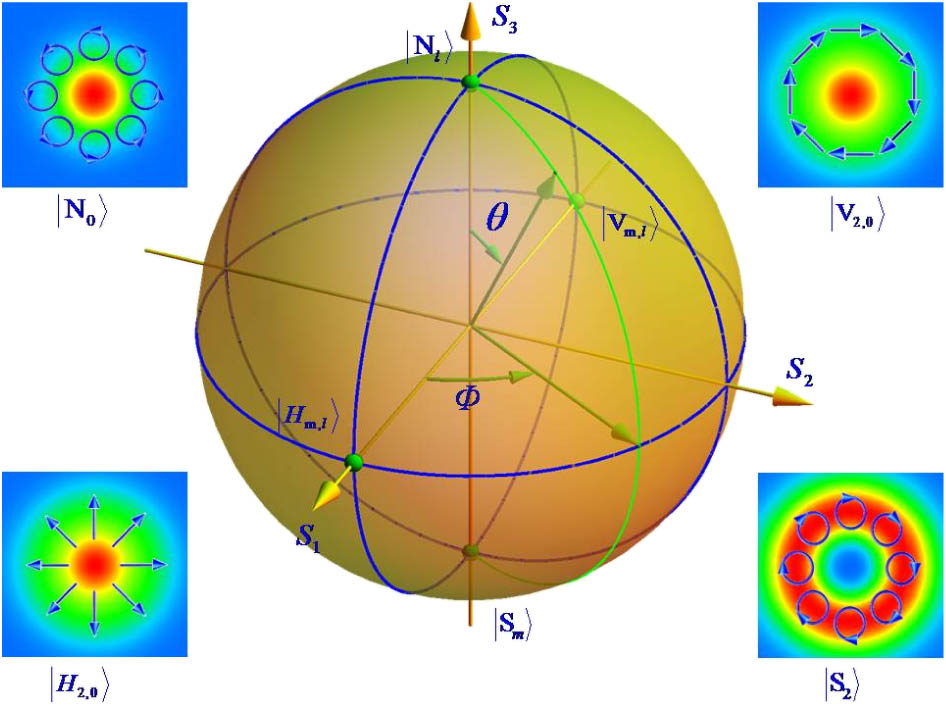
Figure 1.Schematic illustration of the HyOPS. are the spherical coordinates. The north pole and south pole represent orthogonal circularly polarized eigenstates with topological charges of and , and the points and represent the horizontal and vertical polarization bases, respectively. The polarization and intensity distribution of four different points are shown with and .
In the paraxial approximation, a generalized vector vortex beam can be represented as [41] and Here, and are the unit vectors along the and axes in the Cartesian coordinate system. is the angle in the polar coordinate system, and is a constant phase.
On the HyOPS, any point can be represented as a coaxial superposition of these two orthogonal circular polarizations with various coefficients and . The polarization state on the HyOPS is mapped by representing the Stokes parameters in the spherical Cartesian coordinates. These parameters are defined as [40] where , and and are the intensities of and , respectively.
Note that the field described by Eq. (1), by extracting a common phase factor , and neglecting the constant phase , can be transformed into where and .
By comparing Eq. (8) with a general expression of vector beam in Ref. [42], these two coefficients, and , can be regarded as the normalization of and . Here, are the coordinates of the HOPS. Actually, Eq. (9) is derived from the case that homogeneous elliptical polarization light is incident on an inhomogeneous half-wave -plate. It is convenient to assume that the -plate remains stationary. We can thus neglect the factor that is determined by the optical axis distribution in cross section.
Utilizing the relationship resulting from the homomorphism between the physical SU(2) space of the light beam and the topological SO(3) space of the HOPS [43], Eq. (9) is transformed into
Then, it is clear that the second term of Eq. (8) is equivalent to Eq. (10), and it also represents a vector beam on a HOPS. The only difference is that Eq. (8) exhibits an additional spiral phase factor . Therefore, to generate a vector vortex beam described by Eq. (8), we need to add a vortex phase into the vector beam. To generate a vortex phase, numerous methods have been developed so far, such as spiral phase plates [9], spatial light modulators [44–47], diffractive elements [48], and fork gratings [49]. Comparing with other methods, a spiral phase plate can usually obtain much higher efficiency with less complicated structure. Therefore, a spiral phase plate is employed in our work. After adding a vortex phase, the generated vector beam is converted into a vector vortex beam, i.e., the conversion of a point from a HOPS to a HyOPS is realized. Here, we choose to generate the vector vortex beam on the HyOPS with and . The corresponding combination is a half-wave -plate with (Altechna R&D) and a spiral phase plate with . If a vector vortex beam with larger topological charge is desired, larger structure parameters ( and ) are needed. Generally, by choosing the appropriate parameters for the -plate and spiral phase plate, any vector vortex beam represented by Eq. (1) can be realized.
3. EXPERIMENTAL RESULTS AND DISCUSSION
We now establish an experimental setup to generate the vector vortex beam expressed by Eq. (8). As shown in Fig. 2(a), a Glan laser polarizer (GLP1) and a quarter-wave plate (QWP1) convert the laser beam output from the He–Ne laser (beam waist size and operational wavelength ) into an elliptical polarization. Next, the -plate makes the incident elliptically polarized light beam transform into an arbitrary vector beam. The vector beam is finally transformed into a vector vortex beam by the spiral phase plate. Parts (I) and (II) therefore make up a converter that can generate arbitrary vector vortex beams on the HyOPS. As shown in Fig. 2(b), a vector vortex beam can be theoretically decomposed into the vector part and the vortex part. Here, the vector part is generated by part (I) while the vortex part corresponds to part (II).

Figure 2.(a) Experimental setup to generate arbitrary vector vortex beams on the HyOPS. A Gaussian beam emerging from the He–Ne laser (632.8 nm, 17 mW, Thorlabs HNL210L-EC) passes through part (I) (GLP1, QWP1, and QP) to produce a vector beam. Then the vector beam is transformed into a vector vortex beam by part (II) (SPP). Part (III) (QWP2 and GLP2) is used to measure the Stokes parameters. GLP, Glan laser polarizer; QWP, quarter-wave plate; QP, -plate; SPP, spiral phase plate; CCD, charge-coupled device (Coherent LaserCam HR). (b) Schematic illustration of generating a vector vortex beam (right), which can be theoretically decomposed into the vector part (left) and the vortex part (middle).
The structure of the -plate is fabricated by etching space-variant grooves on a fused silica sample using a femtosecond laser, which has a uniform birefringent phase retardation at a wavelength of 632.8 nm. When an intense laser is sharply focused inside the structure, the uniform glass would decompose (), leading to a uniform birefringent phase retardation. This phase retardation is given as , with the writing depth and the induced birefringence. and , where is the filling factor, and and are the refractive indices of the two kinds of porous glasses resulting from the intense laser writing. For a sample with phase retardation, the writing depth is about 80 μm. The line width is 30–50 nm and the filling factor is 0.1–0.2. The silica substrate has a thickness of 3 mm and a diameter of 25.4 mm, while the diameter of the structured area centered on the substrate is 8.0 mm. The optical axis distribution satisfies , where is the spatial rotational rate of the optical axis and is the initial angle. Figures 3(a) and 3(b) respectively show the theoretical and retrieved optical axis distributions of the -plate (). Figures 3(c) and 3(d) are the measured cross polarized images of the -plate under linear polarizers. Here, Fig. 3(b) is calculated from Fig. 3(c) based on the optical Malus law.
Figure 3.(a) and (b) Theoretical and measured optical axis distributions of the -plate (). (c) and (d) Polariscopic images of optical axis distribution of the -plate under crossed polarizers. and stand for the polarization states of the input and output beams, respectively.
As shown in Fig. 4(a), the spiral phase plate is a disk of refractive index in which the thickness increases with the azimuthal angle . Through a spiral phase plate, the incident plane wave shall obtain an phase term and, consequently, has an optical vortex along the transmission axis. Figure 4(b) shows the measured phase retardance value distribution of the spiral phase plate .
Figure 4.(a) and (b) 3D schematic view and measured phase retardance value distribution of spiral phase plate (). (c) and (d) Measured interference patterns of the generated vortex beam with a spherical wave and a plane wave.
Fabrication of spiral phase plates requires several processes, including quantization, exposure, and further development. Practically, we first quantize the 3D surface into 2D bars by using an interval micro-slices are acquired after the quantization. These slices are projected and zoomed to form the 2D binary sub-masks. In the exposure process, the mask is moving at a certain speed, and each quantized unit can acquire the corresponding exposure dose, which is the result of a convolution between the moving speed function and the sub-mask function. After exposure and further development, the 3D structure of a spiral phase plate is finally acquired. The diameter is 25.4 mm. The step height of 1.385 μm enables a phase retardance value ranging from 0 to at a wavelength of 632.8 nm. To verify the generated vortex, the interference patterns of the generated vortex beam with a spherical wave and a plane wave are measured, respectively, corresponding to Figs. 4(c) and 4(d).
To get an arbitrary point on the HyOPS, a detailed relationship of the transformation should be given. Similar to the generation of arbitrary vector beams, in our scheme, the azimuth angle of the outgoing polarization ellipse is equal to the angle between the optical axis direction of QWP1 and the vertical direction. The ellipticity angle is equal to the relative angle of the optical axis direction between GLP1 and QWP1. In addition, a relationship between and can be established: Here the longitude and latitude are, respectively, determined by the optical axis directions of GLP1 and QWP1. The optical axis directions of GLP1 and QWP1 construct 2 degrees of freedom, leading to the evolution of the final state on the surface of the HyOPS. Additionally, the evolution is also associated with the orientation angle of the -plate. By controlling the orientation angle of the -plate, the evolution can be different. A rotation of the -plate by advances the longitude by [40]. The output beam can therefore be selected by rotating the -plate.
We now verify the resultant vector beam and vector vortex beam. Stokes parameters , , and are measured by part (III) in Fig. 2(a) (QWP2 and GLP2) to examine the polarization of the generated vector beams. They are given by [50] Here, is the intensity of light recorded by a CCD, where and are, respectively, the optical axis directions of QWP2 and GLP2 with respect to the vertical direction. The positive angle is chosen as clockwise. By extracting the parameters from the Stokes parameters and utilizing the relationship between Stokes parameters and polarization, the polarization states on the cross section of the generated vector beam are acquired. Figure 5 shows theoretical and experimental polarization states of eight points on the HOPS. It is clear that the experimental results show good agreement with the theory. By depicting the polarization distribution, it is proved intuitively that the generated beams are the desired vector part.
Figure 5.Polarization and intensity distribution of the theoretical and experimental results of vector beams. The first row shows the theoretical results of the points (1,0,0), (0,1,0), and on the HOPS in order from left to right. The second row is the corresponding experimental results. The third row shows the theoretical results of points (0,0,1), , , and on the HOPS. The fourth row is the corresponding experimental results.
In the second part, the spiral phase plate converts the vector beam into a vector vortex beam with an additional topological charge . Here, we choose a spiral phase plate with . The topological charges of the outgoing beam from the spiral phase plate are thus equal to , which are, respectively, 0 and 2 in our scheme. Therefore, the outgoing beam can be regarded as the superposition of a fundamental Gauss beam and a vortex-bearing Laguerre–Gauss beam . Different from the so-called perfect vector vortex beam in Ref. [51] that possesses a stable state of polarization, the mode exhibits a -dependent phase factor . This factor leads to continuously changing polarization accompanying the propagation. To avoid the influence, the CCD is positioned at a fixed distance from the spiral phase plate and the -plate experimentally.
Recently, Yue et al. proposed an integrated approach to generate vector vortex beams based on a reflective-type metasurface [52]. In our experiment, note that the spiral phase plate is positioned sufficiently adjacent to the -plate, so it is possible to construct these two plates on a single silica disk. Our scheme with transmissive-type transformations shall perform as an effective alternative with respect to the reflective-type one. Indeed, we have constructed similar integrated structures based on a single silica disk in the integration of a Pancharatnam–Berry phase lens and a dynamical phase lens [53].
For the resultant vector vortex beam, polarization states in cross section are also acquired, as shown in Fig. 6. It can be seen that Fig. 6 exhibits a certain amount of error in comparison with Fig. 5, in particular a less matched degree of polarization, which we attribute to the imperfect structure of the spiral phase plate. Nevertheless, we still choose to demonstrate the less perfect polarization states of the generated vector vortex beam, which is seldom noted in previous works. Another reason for the errors in both Figs. 5 and 6 is the difficulty of making all the pictures locate at the same pixel, which leads to inaccuracy of calculation. To make up the lack of calculations of polarization states, we also verified the resultant vector vortex beams through traditional polarizer analysis. We choose two typical vector vortex beams, radially and azimuthally polarized light, to verify the polarization by using a polarizer (see Fig. 7). When rotating the polarizer, the recorded intensities in the CCD shows a typical s-shaped pattern whose rotation direction is the same as that of the polarizer, suggesting that the resultant beams are the desired vector vortex beams.
Figure 6.Polarization and intensity distribution of the theoretical and experimental results of vectorial vortex beams. The first row shows the theoretical results of the points (1,0,0), (0,1,0), , and on the HyOPS in order from left to right. The second row is the corresponding experimental results. The third row shows the theoretical results of points (0,0,1), , , and on the HyOPS, The fourth row is the corresponding experimental results.
Figure 7.Intensity distributions of the radially and azimuthally polarized vortex beam behind the polarization analyzer at different angles (represented by the white arrows).
4. CONCLUSION
We have realized the generation of an arbitrary vector vortex beam on the HyOPS. The desired vector vortex beam is decomposed into the vector part and the vortex part. The vector part is generated by a Glan laser polarizer, a quarter-wave plate, and a -plate, and the vortex part is generated by a spiral phase plate. By controlling the optical axis directions of the Glan laser polarizer and quarter-wave plate, any desired vector vortex beam can be obtained. Generally, the resultant vector part, vortex part, and vector vortex beam are in accord with the theory. In addition, this method offers a compact conversion system that shall pave the way for integrated optical devices.
Acknowledgment
Acknowledgment. The authors thank Dr. Zheng Yang for helpful discussions.
References
[1] Q. Zhan. Cylindrical vector beams: from mathematical concepts to applications. Adv. Opt. Photon., 1, 1-57(2009).
[2] L. Allen, M. W. Beijersbergen, R. J. C. Spreeuw, J. P. Woerdman. Orbital angular momentum of light and the transformation of Laguerre–Gaussian laser modes. Phys. Rev. A, 45, 8185-8189(1992).
[3] D. Deng, Q. Guo. Analytical vectorial structure of radially polarized light beams. Opt. Lett., 32, 2711-2713(2007).
[4] W. Shu, Y. Liu, Y. Ke, X. Ling, Z. Liu, B. Huang, H. Luo, X. Yin. Propagation model for vector beams generated by metasurfaces. Opt. Express, 24, 21177-21189(2016).
[5] H. Ye, C. Wan, K. Huang, T. Han, J. Teng, Y. S. Ping, C. Qiu. Creation of vectorial bottle-hollow beam using radially or azimuthally polarized light. Opt. Lett., 39, 630-633(2014).
[6] A. F. Abouraddy, K. C. Toussaint. Three-dimensional polarization control in microscopy. Phys. Rev. Lett., 96, 153901(2006).
[7] X. Xie, Y. Chen, K. Yang, J. Zhou. Harnessing the point-spread function for high-resolution far-field optical microscopy. Phys. Rev. Lett., 113, 263901(2014).
[8] J. Wang, J. Y. Yang, I. M. Fazal, N. Ahmed, Y. Yan, H. Huang, Y. Ren, Y. Yue, S. Dolinar, M. Tur, A. E. Willer. Terabit free-space data transmission employing orbital angular momentum multiplexing. Nat. Photonics, 6, 488-496(2012).
[9] A. M. Yao, M. J. Padgett. Orbital angular momentum: origins, behavior and applications. Adv. Opt. Photon., 3, 161-204(2011).
[10] J. Ng, Z. Lin, C. T. Chan. Theory of optical trapping by an optical vortex beam. Phys. Rev. Lett., 104, 103601(2010).
[11] H. Poincaré. Theorie Mathematique de la Lumiere(1892).
[12] G. Milione, H. I. Sztul, D. A. Nolan, R. R. Alfano. Higher-order Poincaré sphere, Stokes parameters, and the angular momentum of light. Phys. Rev. Lett., 107, 053601(2011).
[13] A. Holleczek, A. Aiello, C. Gabriel, C. Marquardt, G. Leuchs. Classical and quantum properties of cylindrically polarized states of light. Opt. Express, 19, 9714-9736(2011).
[14] Y. Kozawa, S. Sato. Generation of a radially polarized laser beam by use of a conical Brewster prism. Opt. Lett., 30, 3063-3065(2005).
[15] U. Ruiz, P. Pagliusi, C. Provenzano, G. Cipparrone. Highly efficient generation of vector beams through polarization holograms. Appl. Phys. Lett., 102, 161101(2013).
[16] X. Wang, J. Ding, W. Ni, C. Guo, H. Wang. Generation of arbitrary vector beams with a spatial light modulator and a common path interferometric arrangement. Opt. Lett., 32, 3549-3551(2007).
[17] U. Levy, C. H. Tsai, L. Pang, Y. Fainman. Engineering space-variant inhomogeneous media for polarization control. Opt. Lett., 29, 1718-1720(2004).
[18] M. M. Sánchezlópez, J. A. Davis, N. Hashimoto, I. Moreno, E. Hurtado, K. Badham, A. Tanabe, S. W. Delaney. Performance of a q-plate tunable retarder in reflection for the switchable generation of both first- and second-order vector beams. Opt. Lett., 41, 13-16(2016).
[19] Z. Bomzon, G. Biener, V. Kleiner, E. Hasman. Radially and azimuthally polarized beams generated by space-variant dielectric subwavelength gratings. Opt. Lett., 27, 285-287(2002).
[20] R. Oron, S. Blit, N. Davidson, A. A. Friesem. The formation of laser beams with pure azimuthal or radial polarization. Appl. Phys. Lett., 77, 3322-3324(2000).
[21] J. Li, K. Ueda, M. Musha, L. Zhong, A. Shirakawa. Radially polarized and pulsed output from passively Q-switched Nd:YAG ceramic microchip laser. Opt. Lett., 33, 2686-2688(2008).
[22] W. Han, Y. Yang, W. Cheng, Q. Zhan. Vectorial optical field generator for the creation of arbitrarily complex fields. Opt. Express, 21, 20692-20706(2013).
[23] L. Marrucci, C. Manzo, D. Paparo. Optical spin-to-orbital angular momentum conversion in inhomogeneous anisotropic media. Phys. Rev. Lett., 96, 163905(2006).
[24] M. Stadler, M. Schadt. Linearly polarized light with axial symmetry generated by liquid-crystal polarization converters. Opt. Lett., 21, 251-1950(1996).
[25] S. Mei, M. Q. Mehmood, S. Hussain, K. Huang, X. Ling, S. Y. Siew, H. Liu, J. Teng, A. Danner, C. Qiu. Flat helical nanosieves. Adv. Funct. Mater., 26, 5255-5262(2016).
[26] M. Q. Mehmood, S. Mei, S. Hussain, K. Huang, S. Y. Siew, L. Zhang, T. Zhang, X. Ling, H. Liu, J. Teng, A. Danner, S. Zhang, C. Qiu. Visible-frequency metasurface for structuring and spatially multiplexing optical vortices. Adv. Mater., 28, 2533-2539(2016).
[27] A. Arbabi, E. Arbabi, S. M. Kamali, Y. Horie, S. Han, A. Faraon. Miniature optical planar camera based on a wide-angle metasurface doublet corrected for monochromatic aberrations. Adv. Opt. Mater., 4, 818-833(2016).
[28] B. Zhang, Z. Chen, H. Sun, J. Xia, J. Ding. Vectorial optical vortex filtering for edge enhancement. J. Opt., 18, 035703(2016).
[29] Y. Liu, D. Cline, P. He. Vacuum laser acceleration using a radially polarized CO2 laser beam. Nucl. Instrum. Methods Phys. Res., 424, 296-303(1999).
[30] J. Tang, Y. Ming, Z. Chen, W. Hu, F. Xu, Y. Lu. Entanglement of photons with complex spatial structure in Hermite–Laguerre–Gaussian modes. Phys. Rev. A, 94, 012313(2016).
[31] X. Hao, C. Kuang, T. Wang, X. Liu. Phase encoding for sharper focus of the azimuthally polarized beam. Opt. Lett., 35, 3928-3930(2010).
[32] Y. Zhang, P. Li, S. Liu, J. Zhao. Unveiling the photonic spin Hall effect of freely propagating fan-shaped cylindrical vector vortex beams. Opt. Lett., 40, 4444-4447(2015).
[33] Y. Liu, Y. Ke, H. Luo, S. Wen. Photonic spin Hall effect in metasurfaces: a brief review. Nanophotonics, 6, 51-70(2016).
[34] Z. Zhao, J. Wang, S. Li, A. E. Willner. Metamaterials-based broadband generation of orbital angular momentum carrying vector beams. Opt. Lett., 38, 932-934(2013).
[35] C. Qiu, D. Palima, A. Novitsky, D. Gao, W. Ding, S. V. Zhukovsky, J. Gluckstad. Engineering light-matter interaction for emerging optical manipulation applications. Nanophotonics, 3, 181-201(2014).
[36] H. Chen, J. Hao, B. F. Zhang, J. Xu, J. Ding, H. T. Wang. Generation of vector beam with space-variant distribution of both polarization and phase. Opt. Lett., 36, 3179-3181(2011).
[37] F. Cardano, E. Karimi, S. Slussarenko, L. Marrucci, C. de Lisio, E. Santamato. Polarization pattern of vector vortex beams generated by q-plates with different topological charges. Appl. Opt., 51, C1-C6(2012).
[38] E. J. Galvez, S. Khadka, W. H. Schubert, S. Nomoto. Poincaré-beam patterns produced by nonseparable superpositions of Laguerre–Gauss and polarization modes of light. Appl. Opt., 51, 2925-2934(2012).
[39] N. K. Viswanathan, V. V. G. K. Inavalli. Generation of optical vector beams using a two-mode fiber. Opt. Lett., 34, 1189-1191(2009).
[40] X. Yi, Y. Liu, X. Ling, X. Zhou, Y. Ke, H. Luo, S. Wen. Hybrid-order Poincaré sphere. Phys. Rev. A, 91, 023801(2015).
[41] A. Niv, G. Biener, V. Kleiner, E. Hasman. Manipulation of the Pancharatnam phase in vectorial vortices. Opt. Express, 14, 4208-4220(2006).
[42] Y. Liu, X. Ling, X. Yi, X. Zhou, H. Luo, S. Wen. Realization of polarization evolution on higher-order Poincaré sphere with metasurface. Appl. Phys. Lett., 104, 191110(2014).
[43] G. Milione, S. Evans, D. A. Nolan, R. R. Alfano. Higher order Pancharatnam–Berry phase and the angular momentum of light. Phys. Rev. Lett., 108, 190401(2012).
[44] H. Hu, X. Xu, W. Xie, X. Xu. Study on the generation of a vortex laser beam by using phase-only liquid crystal spatial light modulator. Opt. Eng., 52, 091721(2013).
[45] A. S. Ostrovsky, C. Rickenstorffparrao, V. Arrizón. Generation of the “perfect” optical vortex using a liquid-crystal spatial light modulator. Opt. Lett., 38, 534-536(2013).
[46] P. Vaity, L. Rusch. Perfect vortex beam: Fourier transformation of a Bessel beam. Opt. Lett., 40, 597-600(2015).
[47] J. García-García, C. Rickenstorff-Parrao, R. Ramos-García, V. Arrizón, A. S. Ostrovsky. Simple technique for generating the perfect optical vortex. Opt. Lett., 39, 5305-5308(2014).
[48] V. Arrizón, U. Ruiz, D. Sánchez-de-la-Llave, G. Mellado-Villaseñor, A. S. Ostrovsky. Optimum generation of annular vortices using phase diffractive optical elements. Opt. Lett., 40, 1173-1176(2015).
[49] P. Chen, B. Wei, W. Ji, S. Ge, W. Hu, F. Xu, V. Chigrinov, Y. Lu. Arbitrary and reconfigurable optical vortex generation: a high-efficiency technique using director-varying liquid crystal fork gratings. Photon. Res., 3, 133-139(2015).
[50] M. Born, E. Wolf. Principles of Optics(1997).
[51] P. Li, Y. Zhang, S. Liu, C. Ma, L. Han, H. Cheng, J. Zhao. Generation of perfect vectorial vortex beams. Opt. Lett., 41, 10-14(2016).
[52] F. Yue, D. Wen, J. Xin, B. D. Gerardot, J. Li, X. Chen. Vector vortex beam generation with a single plasmonic metasurface. ACS Photon., 3, 1558-1563(2016).
[53] Y. Ke, Y. Liu, J. Zhou, Y. Liu, H. Luo, S. Wen. Optical integration of Pancharatnam–Berry phase lens and dynamical phase lens. Appl. Phys. Lett., 108, 101102(2016).


