• Photonics Research
  • Vol. 6, Issue 5, 363 (2018)
Weiqiang Wang1、2、5、*, Wenfu Zhang1、6、*, Zhizhou Lu1、2, Sai T. Chu3, Brent E. Little1, Qinghua Yang4, Lei Wang1, and Wei Zhao1
Author Affiliations
  • 1State Key Laboratory of Transient Optics and Photonics, Xi’an Institute of Optics and Precision Mechanics (XIOPM), Chinese Academy of Sciences (CAS), Xi’an 710119, China
  • 2University of Chinese Academy of Sciences, Beijing 100049, China
  • 3Department of Physics and Materials Science, City University of Hong Kong, Hong Kong, China
  • 4School of Physics and Optoelectronic Engineering, Xidian University, Xi’an 710071, China
  • 5e-mail: wwq@opt.ac.cn
  • 6e-mail: wfuzhang@opt.ac.cn
  • show less
    DOI: 10.1364/PRJ.6.000363 Cite this Article Set citation alerts
    Weiqiang Wang, Wenfu Zhang, Zhizhou Lu, Sai T. Chu, Brent E. Little, Qinghua Yang, Lei Wang, Wei Zhao. Self-locked orthogonal polarized dual comb in a microresonator[J]. Photonics Research, 2018, 6(5): 363 Copy Citation Text show less
    Device schematic. (a) Schematic of the four-port high-Q MRR. The waveguide core is high-index doped silica glass, which is surrounded by SiO2 cladding. (b) SEM image of the waveguide cross section with 2 μm×3 μm dimension. (c), (d) Calculated mode profiles for TE and TM modes, respectively.
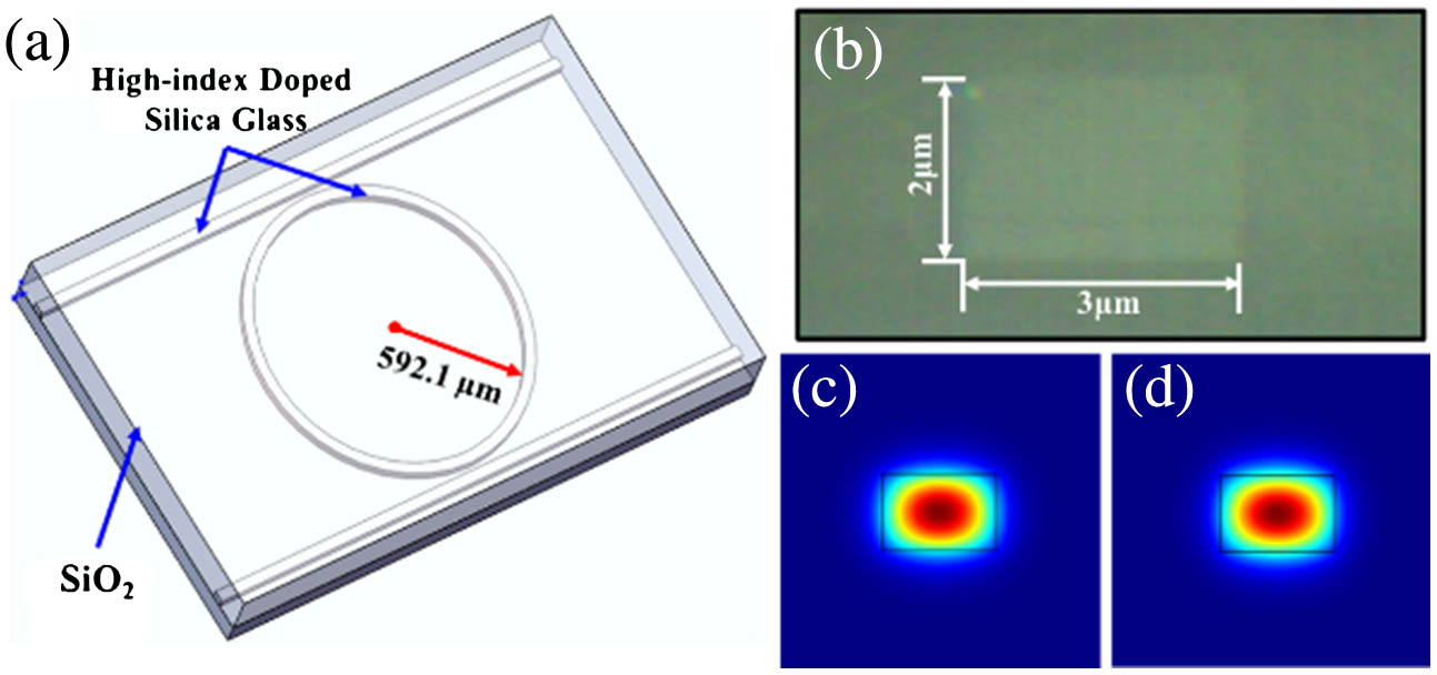
    Fig. 1. Device schematic. (a) Schematic of the four-port high-Q MRR. The waveguide core is high-index doped silica glass, which is surrounded by SiO2 cladding. (b) SEM image of the waveguide cross section with 2  μm×3  μm dimension. (c), (d) Calculated mode profiles for TE and TM modes, respectively.
    Experimental measurement of the device characteristics. (a) Experimental setup for the measurement. The ECDL is a commercial tunable laser with linewidth of 100 kHz. The wavelength is swept from 1520 to 1600 nm in our measurements. The FRR comprises an optical coupler with splitting ratio of 99:1 and a segment fiber with length of ∼6 m. During the measurements, the polarization of the FRR is fixed to one transmission mode, which is used as a ruler to measure the FSR of the MRR. By carefully tuning PC2, the transmission traces of the TE mode and TM mode are measured, respectively. (b), (c) The transmission traces of TE mode and TM mode together with the FRR transmission traces, respectively. (d), (e) The FWHMs of the two vertically polarized modes are 114 MHz and 94 MHz, corresponding to Q-factor of 1.69×10⁶ and 2.05×10⁶, respectively. (f), (g) The measured dispersion curves of the two modes. The FSR of the TM mode is 38 MHz larger than that of the TE mode. ECDL, external cavity diode laser; ISO, isolator; OC, optical coupler; PC, polarization controller; PD, photodetector; MRR, micro-ring resonator; FRR, fiber ring resonator.
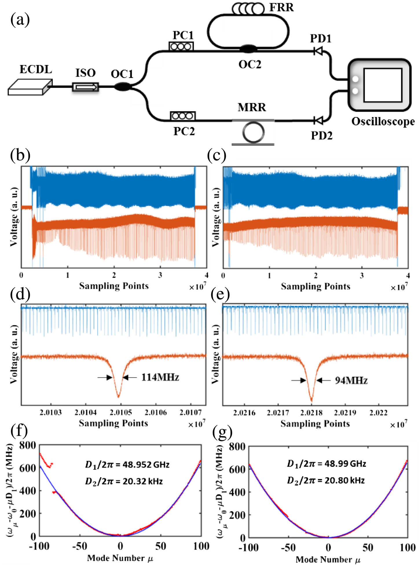
    Fig. 2. Experimental measurement of the device characteristics. (a) Experimental setup for the measurement. The ECDL is a commercial tunable laser with linewidth of 100 kHz. The wavelength is swept from 1520 to 1600 nm in our measurements. The FRR comprises an optical coupler with splitting ratio of 99:1 and a segment fiber with length of 6  m. During the measurements, the polarization of the FRR is fixed to one transmission mode, which is used as a ruler to measure the FSR of the MRR. By carefully tuning PC2, the transmission traces of the TE mode and TM mode are measured, respectively. (b), (c) The transmission traces of TE mode and TM mode together with the FRR transmission traces, respectively. (d), (e) The FWHMs of the two vertically polarized modes are 114 MHz and 94 MHz, corresponding to Q-factor of 1.69×10⁶ and 2.05×10⁶, respectively. (f), (g) The measured dispersion curves of the two modes. The FSR of the TM mode is 38 MHz larger than that of the TE mode. ECDL, external cavity diode laser; ISO, isolator; OC, optical coupler; PC, polarization controller; PD, photodetector; MRR, micro-ring resonator; FRR, fiber ring resonator.
    Schematic of the orthogonal polarized dual-comb generation experiment. EDFA, erbium-doped fiber amplifier; ISO, isolator; PC, polarization controller; MRR, micro-ring resonator; TBPF, tunable bandpass filter; OC, optical coupler; PBS, polarization beam splitter; TE, transverse electric; TM, transverse magnetic.
    Fig. 3. Schematic of the orthogonal polarized dual-comb generation experiment. EDFA, erbium-doped fiber amplifier; ISO, isolator; PC, polarization controller; MRR, micro-ring resonator; TBPF, tunable bandpass filter; OC, optical coupler; PBS, polarization beam splitter; TE, transverse electric; TM, transverse magnetic.
    Experimental results of the orthogonal polarized dual comb. (a) Optical spectrum of the orthogonal polarized dual comb with over 300 nm bandwidth. The two pumps are located at around 1558 nm. (b)–(d) Enlarged drawing of the orthogonal dual comb at around wavelengths 1530, 1558, and 1590 nm, respectively. (e), (f) The optical spectra of separated TM- and TE-polarized combs.
    Fig. 4. Experimental results of the orthogonal polarized dual comb. (a) Optical spectrum of the orthogonal polarized dual comb with over 300 nm bandwidth. The two pumps are located at around 1558 nm. (b)–(d) Enlarged drawing of the orthogonal dual comb at around wavelengths 1530, 1558, and 1590 nm, respectively. (e), (f) The optical spectra of separated TM- and TE-polarized combs.
    Beating RF spectra of comb line pairs located at around 1558.8, 1567.7, 1576.7, 1585.7, and 1594. 9 nm.
    Fig. 5. Beating RF spectra of comb line pairs located at around 1558.8, 1567.7, 1576.7, 1585.7, and 1594. 9 nm.
    Weiqiang Wang, Wenfu Zhang, Zhizhou Lu, Sai T. Chu, Brent E. Little, Qinghua Yang, Lei Wang, Wei Zhao. Self-locked orthogonal polarized dual comb in a microresonator[J]. Photonics Research, 2018, 6(5): 363
    Download Citation