
Yuanbin Jin, Jiangwei Yan, Shah Jee Rahman, Jie Li, Xudong Yu, Jing Zhang, "6 GHz hyperfast rotation of an optically levitated nanoparticle in vacuum," Photonics Res. 9, 1344 (2021)
- Photonics Research
- Vol. 9, Issue 7, 1344 (2021)
Abstract
1. INTRODUCTION
In recent years, levitated nanoparticles in vacuum have attracted considerable interest and become an important platform for ultrasensitive force detection [1–3], the study of macroscopic quantum phenomena [4–8], and nonequilibrium thermodynamics [9–12], among many others. Over the past decade, significant progress has been made in the experimental realization of cooling the motion of trapped nanoparticles [13–21] and the motional quantum ground state has been achieved [6]. Such a system has also been employed for the fundamental test of unconventional decoherence theories at the macro scale [22–28]. In Refs. [23–28] the relevant degree of freedom of motion is the center-of-mass (CoM) motion. Other degrees of freedom of motion of the levitated nanoparticle, such as the torsional vibration [29], the precession motion [30], and rotation [31–36], also provide rich physics to explore. Recent theoretical work [37,38] shows that the rotational degree of freedom may offer considerable advantages in testing the continuous-spontaneous-localization collapse theory. Furthermore, hyperfast rotation [34–36] has many important applications, such as in testing material properties in extreme conditions [39] and detecting the quantum form of rotational friction [40]. Recently, a hyperfast rotation of frequency 5.2 GHz (700 MHz) of a trapped nanodumbbell (nanosphere) has been reported [36]. The rotation of a nanodumbbell is much faster than that of a nanosphere in the same size because it receives a much larger optical torque under the same trap and air pressure.
Stable optical levitation at low and high vacuum can be achieved without feedback cooling of the microparticle’s and nanoparticle’s motion. However, feedback cooling of the CoM motion is typically required to prevent particle loss from the trap at intermediate pressure (around 100 Pa), where photophoretic forces, sphere de-gassing, and other sources of noise not present in high vacuum may play significant roles [41]. In previous works, the hyperfast rotation [34–36] is observed for a horizontally propagating trapping beam with using feedback cooling to reach low pressure. A vertically propagating trapping beam with a low NA is adopted to levitate the micrometer-sized spheres [42], in which feedback cooling is also used to reach low pressure and megahertz rotation is obtained [33]. In this work, we show that, by adopting a vertical-up layout of the trapping beam and using a high-NA objective lens to focus this laser, we can stably trap a nanoparticle from an atmospheric pressure to high vacuum (
2. TRAP NANOPARTICLE FROM ATMOSPHERIC TO LOW PRESSURE WITHOUT USING FEEDBACK COOLING
The experimental setup is depicted in Fig. 1. We optically trap an amorphous silica nanoparticle in vacuum using a TEM00 Gaussian mode 1064 nm laser in gravity direction. The laser first passes through an acousto-optic modulator (AOM) for shifting the frequency and controlling the power. The frequency-shifted laser is then coupled into a single-mode polarization-maintaining fiber, of which the output beam passes successively through a quarter- and a half-wave plates. The vertically propagating 1064 nm laser is strongly focused by a high-NA objective lens [Nikon CF IC EPI Plan 100X, the NA is 0.95 and the working distance (WD) is 0.3 mm] in a vacuum chamber for trapping the particles. The polarization of the light can be adjusted precisely by the combination of the two wave plates. The power of the laser before entering the chamber is 300 mW, and the total transmission of the chamber window and the objective lens is about 52%, leading to an effective trapping power of about 156 mW in our experiment. The diameter of the trapping laser is 3.2 mm before entering the objective lens and about 1.1 μm at the focus point. The intensity distribution in the
Sign up for Photonics Research TOC. Get the latest issue of Photonics Research delivered right to you!Sign up now
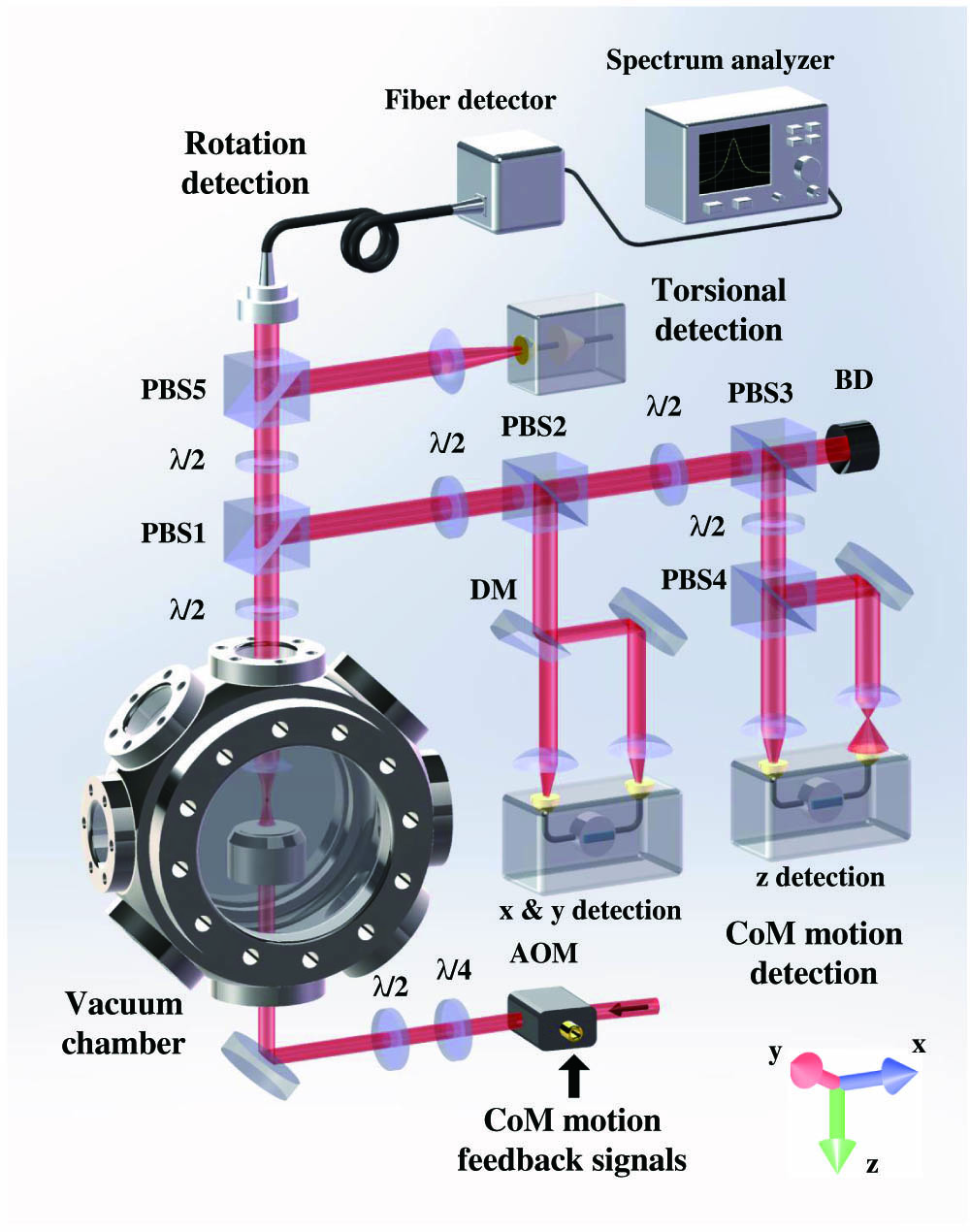
Figure 1.Schematic diagram of the experimental setup, which includes five parts: vacuum system, rotation detection, torsional vibration detection, CoM motion detection, and feedback system. AOM, acousto-optic modulator;
A small dielectric particle in a strongly focused light beam feels a three-dimensional gradient force. In this situation, two relevant effects must be considered. First, for a single trapping beam configuration, the axial trapping force is crucial because the axial gradient force is small compared to the radial direction. In addition, in the axial direction, the particle also feels a scattering force from the light, which tends to push the particle out of the trap. Consequently, the equilibrium position of the particle is moved away from the focus point along the propagating direction of the trapping light, which decreases the well depth in this direction. Hence, for a horizontal layout of the trapping beam, a high-NA lens is usually used to focus the beam and provides a large axial gradient force. As a result, the power density near the focus point is relatively high in this case. Second, in high vacuum the thermal transfer between the particle and the background gases is restrained. Therefore, the particle is heated to a high and uniform internal temperature. In parallel, in low vacuum the particle has a low and also uniform internal temperature due to a quick heat exchange between the nanoparticle and the air molecules. However, there are internal temperature gradients induced by the trapping laser at intermediate pressure, leading to a nonuniform distribution of temperature on the nanoparticle surface. When air molecules hit the nanoparticle, the rebounding from the warmer side will have higher energy than the rebounding from the cooler side. This imparts a net force (i.e., the photophoretic force) on the particle, which is in the vertical-up direction in our system. This force can easily kick the particle out of the trap at intermediate pressure [41]. Therefore, the feedback cooling of the CoM motion is generally required to stabilize the trap for the horizontal layout of the trapping beam because of the remarkable photophoretic force induced by the relatively large power density and the finite heat dissipation at intermediate pressure. Although a vertical-up layout for the trapping beam is also adopted in Refs. [33,41,42], in their experiment, the NA of the focusing lens is small, and thus the power density near the focus point is relatively low. Consequently, the well is shallow, and the corresponding gradient force is weak. Therefore, the feedback cooling is also required to make their trap stable at intermediate pressure. To restrain these detrimental effects, we implement a vertical-up layout for the trapping light and use a high-NA objective lens to strongly focus this beam, which can effectively compensate the influences of the scattering and photophoretic forces using its own gravity of the particle and simultaneously provide a large well depth. As a result, we can stably trap a nanoparticle from an atmospheric pressure to high vacuum without using feedback cooling. This results in about 50% success probability of trapping a nanoparticle below an intermediate pressure 100 Pa to lower pressures. Furthermore, we can monitor the intensity of the scattering light from the trapping laser by imaging the nanoparticle via a charge-coupled device camera. By further selecting the nanoparticles at atmospheric pressure with an intermediate scattering intensity, we can increase the success probability to more than 90% below an intermediate pressure. Those nanoparticles with much higher or lower intensity of the scattering light cannot reach high vacuum in our experiment.
The trapped nanoparticle in the well can do translational motion, i.e., CoM motion, which generally has three eigen frequencies in three directions due to the vector diffraction of the light [43]. In our experiment, the eigen frequencies in the
3. ROTATION WITHOUT USING FEEDBACK COOLING
The angular momentum of the trapping light can be transferred to the nanoparticle due to the absorption, birefringence, and asymmetric shape of the particle [34]. The transferred angular momentum provides a torque, which drives the particle to rotate. For an amorphous perfect nanosphere, the driving torque is only determined by the absorption of the doping impurity and the medium itself. For an imperfect nanosphere, the asymmetric shape can also induce a driving torque. We denote the total driving torque the particle receives as
Considering the circularly polarized trapping laser, the total driving torque is proportional to the light intensity:
![]()
Figure 2.Measured rotation frequency versus the power of a near circularly polarized trapping laser at 1 Pa. The mass of the nanoparticle is about
![]()
Figure 3.Measured rotation frequency versus the angle of the fast axis of the quarter-wave plate at different pressures. The red, green, and purple traces are measured at 5 Pa, 0.5 Pa, and 0.1 Pa, respectively. The dashed lines are the corresponding theoretical fittings using
In order to observe the rotation of the nanoparticle, we first trap the nanoparticle below an intermediate pressure 100 Pa to lower pressures with success probability more than 90%, and we then can observe the rotation in high vacuum with probability of about 90%. In Fig. 4(a), we measure the rotation frequency of three trapped nanoparticles versus the air pressure for a fixed laser power of 300 mW without feedback cooling. We use two vacuum gauges, a resistance gauge with measurement range from
![]()
Figure 4.The experimental results without feedback cooling. (a) Measured rotation frequency of three trapped nanoparticles (green, blue, and red traces) versus air pressure without feedback cooling. The masses of the three nanoparticles are about
The rotation and the CoM motion can influence each other, which leads to the coupling of the two motions. On the one hand, a large amplitude of the CoM motion causes a large change of the laser strength that the nanoparticle feels, and consequently induces a large fluctuation of the rotation frequency (the rotation frequency depends on the strength of the trapping laser). On the other hand, when
4. ROTATION WITH FEEDBACK COOLING
In order to reduce those deleterious factors, we further implement feedback controls to cool the CoM motion of the nanoparticle in three directions (see Fig. 1). The displacement signals in three directions are sent into broad-bandwidth lock-in amplifiers (Zurich Instruments HF2LI 50 MHz) for generating the corresponding double-frequency signals, which are then input into a function generator of AOM for modulating the power of the trapping laser and cooling the CoM motions [47]. This parametric feedback cooling results in significantly improved stability of the trap. Figures 5(a) and 5(b) illustrate the fluctuation of the rotation frequency before and after the feedback cooling at 0.16 Pa, respectively. Figure 5(c) shows the rotation frequencies versus the air pressure with feedback cooling for three different nanoparticles. The highest rotation frequency observed is about 6 GHz at
![]()
Figure 5.The fluctuation of the rotation frequency (a) without feedback cooling and (b) with feedback cooling at 0.16 Pa. We sample the rotation frequency 30 times per second. (c) Measured rotation frequency of three trapped nanoparticles (green, blue, and red traces) versus air pressure with feedback cooling. The masses of the three nanoparticles are about
5. DISCUSSION
In this paper, we have adopted a vertical-up layout of the trapping light and used a high-NA objective lens to strongly focus this beam in an optical levitation system, which allows us to trap a nanoparticle from an atmospheric pressure to high vacuum without using feedback cooling. Consequently, we measure a maximum rotation frequency of 4.3 GHz without feedback cooling. Apparently, without using feedback controls, the experiment will be more compact and cost-saving. Trapped nanoparticles in high vacuum promise many important studies, such as Refs. [1–12]. Therefore, our work (trapping without feedback controls) will find important applications in the above studies. By further including feedback cooling, we have measured a record high rotation frequency about 6 GHz. In our experiment, the rotation is hyperfast and close to the regime where the internal forces generated were strong enough to break up the material. Our work thus provides an important platform for studying vacuum friction and the material properties under extreme conditions. The system can also be used for ultrasensitive torque detection [36] and micrometer-scale pressure gauges [48]. Furthermore, our work sheds light on the test of the continuous-spontaneous-localization collapse theory by using the rotational degrees of freedom [37,38].
APPENDIX A: LOADING PROCESS
To load the nanoparticle, we tried amorphous silica nanoparticles produced by different manufacturers, and finally selected the nonfunctionalized silica nanoparticle (Bangs Laboratories, Inc.), which gave us the best result. Its nominal diameter is about 170?nm with the range of 20%. The hydro-soluble silica nanoparticles are first diluted in the high-purity ethanol with a concentration of about
References
[1] G. Ranjit, D. P. Atherton, J. H. Stutz, M. Cunningham, A. A. Geraci. Attonewton force detection using microspheres in a dual-beam optical trap in high vacuum. Phys. Rev. A, 91, 051805(2015).
[2] G. Ranjit, M. Cunningham, K. Casey, A. A. Geraci. Zeptonewton force sensing with nanospheres in an optical lattice. Phys. Rev. A, 93, 053801(2016).
[3] V. Jain, J. Gieseler, C. Moritz, C. Dellago, R. Quidant, L. Novotny. Direct measurement of photon recoil from a levitated nanoparticle. Phys. Rev. Lett., 116, 243601(2016).
[4] M. Aspelmeyer, T. J. Kippenberg, F. Marquardt. Cavity optomechanics. Rev. Mod. Phys., 86, 1391-1452(2014).
[5] M. Arndt, K. Hornberger. Testing the limits of quantum mechanical superpositions. Nat. Phys., 10, 271-277(2014).
[6] U. Delić, M. Reisenbauer, K. Dare, D. Grass, V. Vuletić, N. Kiesel, M. Aspelmeyer. Cooling of a levitated nanoparticle to the motional quantum ground state. Science, 367, 892-895(2020).
[7] J. Millen, T. S. Monteiro, R. Pettit, A. N. Vamivakas. Optomechanics with levitated particles. Rep. Prog. Phys., 83, 026401(2020).
[8] B. A. Stickler, K. Hornberger, M. S. Kim. Quantum rotations of nanoparticles(2021).
[9] T. Li, S. Kheifets, D. Medellin, M. G. Raizen. Measurement of the instantaneous velocity of a Brownian particle. Science, 328, 1673-1675(2010).
[10] T. M. Hoang, R. Pan, J. Ahn, J. Bang, H. T. Quan, T. Li. Experimental test of the differential fluctuation theorem and a generalized Jarzynski equality for arbitrary initial states. Phys. Rev. Lett., 120, 080602(2018).
[11] J. Gieseler, R. Quidant, C. Dellago, L. Novotny. Dynamic relaxation of a levitated nanoparticle from a non-equilibrium steady state. Nat. Nanotechnol., 9, 358-364(2014).
[12] J. Millen, T. Deesuwan, P. Barker, J. Anders. Nanoscale temperature measurements using non-equilibrium Brownian dynamics of a levitated nanosphere. Nat. Nanotechnol., 9, 425-429(2014).
[13] T. Li, S. Kheifets, M. G. Raizen. Millikelvin cooling of an optically trapped microsphere in vacuum. Nat. Phys., 7, 527-530(2011).
[14] J. Gieseler, B. Deutsch, R. Quidant, L. Novotny. Subkelvin parametric feedback cooling of a laser-trapped nanoparticle. Phys. Rev. Lett., 109, 103603(2012).
[15] N. Kiesel, F. Blaser, U. Delić, D. Grass, R. Kaltenbaek, M. Aspelmeyer. Cavity cooling of an optically levitated submicron particle. Proc. Natl. Acad. Sci. USA, 110, 14180-14185(2013).
[16] P. Asenbaum, S. Kuhn, S. Nimmrichter, U. Sezer, M. Arndt. Cavity cooling of free silicon nanoparticles in high vacuum. Nat. Commun., 4, 2743(2013).
[17] J. Millen, P. Z. G. Fonseca, T. Mavrogordatos, T. S. Monteiro, P. F. Barker. Cavity cooling a single charged levitated nanosphere. Phys. Rev. Lett., 114, 123602(2015).
[18] D. Windey, C. Gonzalez-Ballestero, P. Maurer, L. Novotny, O. Romero-Isart, R. Reimann. Cavity-based 3D cooling of a levitated nanoparticle via coherent scattering. Phys. Rev. Lett., 122, 123601(2019).
[19] U. C. V. Delić, M. Reisenbauer, D. Grass, N. Kiesel, V. Vuletić, M. Aspelmeyer. Cavity cooling of a levitated nanosphere by coherent scattering. Phys. Rev. Lett., 122, 123602(2019).
[20] Y. Zheng, G.-C. Guo, F.-W. Sun. Cooling of a levitated nanoparticle with digital parametric feedback. Appl. Phys. Lett., 115, 101105(2019).
[21] F. Tebbenjohanns, M. Frimmer, V. Jain, D. Windey, L. Novotny. Motional sideband asymmetry of a nanoparticle optically levitated in free space. Phys. Rev. Lett., 124, 013603(2020).
[22] A. Bassi, K. Lochan, S. Satin, T. P. Singh, H. Ulbricht. Models of wave-function collapse, underlying theories, and experimental tests. Rev. Mod. Phys., 85, 471-527(2013).
[23] O. Romero-Isart. Quantum superposition of massive objects and collapse models. Phys. Rev. A, 84, 052121(2011).
[24] J. Li, S. Zippilli, J. Zhang, D. Vitali. Discriminating the effects of collapse models from environmental diffusion with levitated nanospheres. Phys. Rev. A, 93, 050102(2016).
[25] D. Goldwater, M. Paternostro, P. F. Barker. Testing wave-function-collapse models using parametric heating of a trapped nanosphere. Phys. Rev. A, 94, 010104(2016).
[26] A. Vinante, A. Pontin, M. Rashid, M. Toroš, P. F. Barker, H. Ulbricht. Testing collapse models with levitated nanoparticles: detection challenge. Phys. Rev. A, 100, 012119(2019).
[27] D. Zheng, Y. Leng, X. Kong, R. Li, Z. Wang, X. Luo, J. Zhao, C.-K. Duan, P. Huang, J. Du, M. Carlesso, A. Bassi. Room temperature test of the continuous spontaneous localization model using a levitated micro-oscillator. Phys. Rev. Res., 2, 013057(2020).
[28] A. Pontin, N. P. Bullier, M. Toroš, P. F. Barker. Ultranarrow-linewidth levitated nano-oscillator for testing dissipative wave-function collapse. Phys. Rev. Res., 2, 023349(2020).
[29] T. M. Hoang, Y. Ma, J. Ahn, J. Bang, F. Robicheaux, Z.-Q. Yin, T. Li. Torsional optomechanics of a levitated nonspherical nanoparticle. Phys. Rev. Lett., 117, 123604(2016).
[30] M. Rashid, M. Toroš, A. Setter, H. Ulbricht. Precession motion in levitated optomechanics. Phys. Rev. Lett., 121, 253601(2018).
[31] Y. Arita, M. Mazilu, K. Dholakia. Laser-induced rotation and cooling of a trapped microgyroscope in vacuum. Nat. Commun., 4, 2374(2013).
[32] S. Kuhn, B. A. Stickler, A. Kosloff, F. Patolsky, K. Hornberger, M. Arndt, J. Millen. Optically driven ultra-stable nanomechanical rotor. Nat. Commun., 8, 1670(2017).
[33] F. Monteiro, S. Ghosh, E. C. van Assendelft, D. C. Moore. Optical rotation of levitated spheres in high vacuum. Phys. Rev. A, 97, 051802(2018).
[34] R. Reimann, M. Doderer, E. Hebestreit, R. Diehl, M. Frimmer, D. Windey, F. Tebbenjohanns, L. Novotny. GHz rotation of an optically trapped nanoparticle in vacuum. Phys. Rev. Lett., 121, 033602(2018).
[35] J. Ahn, Z. Xu, J. Bang, Y.-H. Deng, T. M. Hoang, Q. Han, R.-M. Ma, T. Li. Optically levitated nanodumbbell torsion balance and GHz nanomechanical rotor. Phys. Rev. Lett., 121, 033603(2018).
[36] J. Ahn, Z. Xu, J. Bang, P. Ju, X. Gao, T. Li. Ultrasensitive torque detection with an optically levitated nanorotor. Nat. Nanotechnol., 15, 89-93(2020).
[37] B. Schrinski, B. A. Stickler, K. Hornberger. Collapse-induced orientational localization of rigid rotors. J. Opt. Soc. Am. B, 34, C1-C7(2017).
[38] M. Carlesso, M. Paternostro, H. Ulbricht, A. Vinante, A. Bassi. Non-interferometric test of the continuous spontaneous localization model based on rotational optomechanics. New J. Phys., 20, 083022(2018).
[39] M. Schuck, D. Steinert, T. Nussbaumer, J. W. Kolar. Ultrafast rotation of magnetically levitated macroscopic steel spheres. Sci. Adv., 4, e1701519(2018).
[40] R. Zhao, A. Manjavacas, F. J. Garca de Abajo, J. B. Pendry. Rotational quantum friction. Phys. Rev. Lett., 109, 123604(2012).
[41] F. Monteiro, W. Li, G. Afek, C.-L. Li, M. Mossman, D. C. Moore. Force and acceleration sensing with optically levitated nanogram masses at microkelvin temperatures. Phys. Rev. A, 101, 053835(2020).
[42] F. Monteiro, S. Ghosh, A. G. Fine, D. C. Moore. Optical levitation of 10-ng spheres with nano-
[43] Y. Jin, X. Yu, J. Zhang. Polarization-dependent center-of-mass motion of an optically levitated nanosphere. J. Opt. Soc. Am. B, 36, 2369-2377(2019).
[44] J. Fremerey. Spinning rotor vacuum gauges. Vacuum, 32, 685-690(1982).
[45] L. Shao, D. Andrén, S. Jones, P. Johansson, M. Käll. Optically controlled stochastic jumps of individual gold nanorod rotary motors. Phys. Rev. B, 98, 085404(2018).
[46] M. E. J. Friese, T. A. Nieminen, N. R. Heckenberg, H. Rubinsztein-Dunlop. Optical alignment and spinning of laser-trapped microscopic particles. Nature, 394, 348-350(1998).
[47] J. Vovrosh, M. Rashid, D. Hempston, J. Bateman, M. Paternostro, H. Ulbricht. Parametric feedback cooling of levitated optomechanics in a parabolic mirror trap. J. Opt. Soc. Am. B, 34, 1421-1428(2017).
[48] C. P. Blakemore, D. Martin, A. Fieguth, A. Kawasaki, N. Priel, A. D. Rider, G. Gratta. Absolute pressure and gas species identification with an optically levitated rotor. J. Vac. Sci. Technol. B, 38, 024201(2020).


Set citation alerts for the article
Please enter your email address

© Copyright 2018-2021 | Chinese Laser Press. All Rights Reserved 沪ICP备15018463号-20