• Chinese Journal of Lasers
  • Vol. 48, Issue 13, 1304001 (2021)
Liang Yang1、* and Ning Zhang2、**
Author Affiliations
  • 1College of Information Engineering, Eastern Liaoning University, Dandong, Liaoning 118003, China
  • 2The Third Space Optics Research Section, Changchun Institute of Optics, Fine Mechanics and Physics, Chinese Academy of Sciences, Changchun, Jilin 130033, China
  • show less
    DOI: 10.3788/CJL202148.1304001 Cite this Article Set citation alerts
    Liang Yang, Ning Zhang. Measurement System Design of Spatial Position Accuracy of Dynamic Targets[J]. Chinese Journal of Lasers, 2021, 48(13): 1304001 Copy Citation Text show less
    Schematic of dynamic target
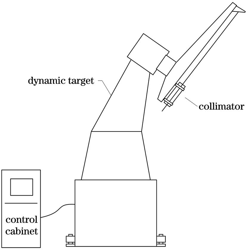
    Fig. 1. Schematic of dynamic target
    Structural diagram of measurement platform
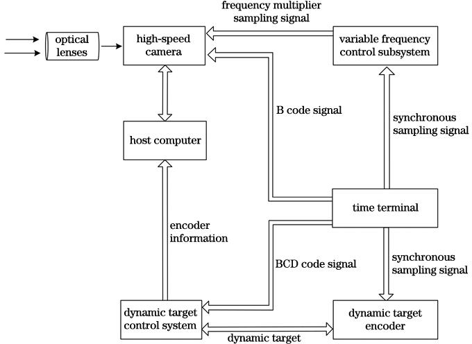
    Fig. 2. Structural diagram of measurement platform
    Schematic of measurement system
    Fig. 3. Schematic of measurement system
    Target motion trajectory
    Fig. 4. Target motion trajectory
    Corresponding relation between θ and ΔA
    Fig. 5. Corresponding relation between θ and ΔA
    Corresponding relation between θ and ΔE
    Fig. 6. Corresponding relation between θ and ΔE
    Space motion coordinates of dynamic target
    Fig. 7. Space motion coordinates of dynamic target
    Relationship between image plane coordinates and dynamic target coordinates
    Fig. 8. Relationship between image plane coordinates and dynamic target coordinates
    Schematic of image plane rotation
    Fig. 9. Schematic of image plane rotation
    Static reference point trajectory at medium speed
    Fig. 10. Static reference point trajectory at medium speed
    Image surface offset trajectory of static reference point at medium speed
    Fig. 11. Image surface offset trajectory of static reference point at medium speed
    Dynamic motion trajectory at medium speed
    Fig. 12. Dynamic motion trajectory at medium speed
    Corresponding relation between horizontal offset and coder angle
    Fig. 13. Corresponding relation between horizontal offset and coder angle
    Corresponding relation between vertical offset and coder angle
    Fig. 14. Corresponding relation between vertical offset and coder angle
    Target motion stateDynamic error0° position90° position135° position180° position
    Rotation clockwise with 3.6 (°)·s-1σA1.64″2.05″0.85″1.17″
    σE2.74″3.44″0.78″1.96″
    Rotation counterclockwise with 3.6 (°)·s-1σA1.28″1.16″0.78″1.89″
    σE3.50″2.92″0.52″2.05″
    Rotation clockwise with 12 (°)·s-1σA1.88″1.74″1.18″1.64″
    σE1.01″0.69″0.82″1.35″
    Rotation counterclockwise with 12 (°)·s-1σA1.86″1.01″0.46″0.71″
    σE2.17″1.56″0.94″1.31″
    Rotation clockwise with 72 (°)·s-1σA4.01″1.55″1.12″3.68″
    σE1.49″1.20″1.43″2.31″
    Rotation counterclockwise with 72 (°)·s-1σA1.57″1.81″3.19″3.74″
    σE1.33″3.90″3.53″1.23″
    Table 1. Dynamic accuracy
    Liang Yang, Ning Zhang. Measurement System Design of Spatial Position Accuracy of Dynamic Targets[J]. Chinese Journal of Lasers, 2021, 48(13): 1304001
    Download Citation