X-ray beams carrying orbital angular momentum (OAM) are an emerging tool for probing matter. Optical elements, such as spiral phase plates and zone plates, have been widely used to generate OAM light. However, due to the high impinging intensities, these optics are challenging to use at X-ray free-electron lasers (XFELs). Here, we propose a self-seeded free-electron laser (FEL) method to produce intense X-ray vortices. Unlike passive filtering after amplification, an optical element will be used to introduce the helical phase to the radiation pulse in the linear regime, significantly reducing thermal load on the optical element. The generated OAM pulse is then used as a seed and significantly amplified. Theoretical analysis and numerical simulations demonstrate that the power of the OAM seed pulse can be amplified by more than two orders of magnitude, reaching peak powers of several tens of gigawatts. The proposed method paves the way for high-power and high-repetition-rate OAM pulses of XFEL light.
Structured light could provide new perspectives on numerous physical phenomena. In particular, optical vortices carrying orbital angular momentum (OAM),1 characterized by a helical phase-front , where is the azimuthal coordinate and is the topological charge, are intensively studied. OAM light at visible and infrared wavelengths has been used in a wide range of fields.2–7 In the short wavelength range, optical vortices are promising means to trigger new phenomena through light–matter interaction.8–10 X-ray beams carrying OAM have been proposed for research in quadrupolar X-ray dichroism experiments,11 photoionization experiments,12 resonant inelastic X-ray scattering,13 and magnetic helicoidal dichroism.14,15 Most recently, a new type of phase dichroism has been demonstrated to probe the real-space configuration of the antiferromagnetic ground state with X-ray beams carrying OAM.16 Moreover, the hard X-ray helical dichroism of disordered molecular media has been demonstrated.17 At present, X-ray OAM light is provided by synchrotron radiation facilities. The generation of high-intensity X-ray OAM beams by X-ray free-electron lasers (XFELs) could open new possibilities for studies requiring well-defined spatial intensity and phase variations.
Modern XFELs deliver high-brightness pulses with durations spanning from tens of femtoseconds down to the attosecond range, enabling new research in a variety of scientific fields.18,19 The majority of XFEL facilities worldwide20–24 employ the mechanism of self-amplified spontaneous emission (SASE).25 The SASE process starts from the initial electron-beam shot noise and allows operation over a wide spectral range, reaching sub-angstrom wavelengths. Self-seeding schemes26,27 are used at several facilities to enhance the temporal coherence of free-electron laser (FEL) pulses while increasing their spectral density. However, the transverse radiation profile of FELs operating at saturation is restricted to the fundamental FEL mode, which can usually be approximated by a Gaussian mode with no azimuthal phase dependence.
The generation of OAM light at XFELs can be realized by using helical undulators or forming electron bunches with helical shapes. In the first case, the harmonic radiation in helical undulators has long been theoretically shown to carry a helical phase,28–30 but which was experimentally demonstrated only recently.31–33 However, the intensity of the harmonic emission is much weaker than that of the fundamental.29 In order to deal with this issue, harmonic interaction between a seed laser and an electron beam in a helical undulator34,35 was further proposed to generate OAM radiation at the fundamental wavelength. In addition, schemes to generate OAM radiation by using an external seed laser with a proper transverse phase structure to form the electron bunches into a helical pattern36,37 have been proposed. However, these methods are limited by the availability of external seed lasers, or by the harmonic conversion number, especially at the shortest wavelengths. Also, a transverse-mode selection method using Bragg reflectors and longitudinal transverse-mode coupling38 has been proposed, but it requires an XFEL oscillator configuration.
Sign up for Advanced Photonics Nexus TOC. Get the latest issue of Advanced Photonics Nexus delivered right to you!Sign up now
A more straightforward approach to generate X-ray OAM light is to employ optical elements, such as spiral phase plates (SPPs),39,40 spiral Fresnel zone plates (SZPs),41,42 and other diffractive optics43 behind an undulator. In recent years, these optical elements have been well developed and have been experimentally demonstrated to produce soft and hard X-ray OAM light at synchrotron light sources. The design of an SPP typically features a rotating step with increasing thickness in the azimuthal direction. As the light beam passes through the SPP, it collects an azimuthally varying phase, transforming it into a beam with a helical phase.44 Recently, SPPs made from fused silica40 have been successfully used to shape synchrotron radiation at photon energies of 8.2 keV, and are considered for potential use at XFELs. In addition, the SZP is a unique class of diffractive optics that not only imparts a spiral phase to the incoming beam but also exhibits focusing properties. SZPs with silicon membranes have been successfully used at an FEL in the extreme-ultraviolet wavelength range with an efficiency of 17% and a pulse energy of around .33 However, for obtaining X-ray OAM radiation with high pulse energies, the efficiency and thermal loading of these optics can constitute a significant challenge, especially considering the development of high-repetition-rate XFELs based on superconducting accelerators.
In this work, we propose a new scheme to generate intense X-ray vortices that is free from the previous issues. The method is based on the widely used SASE mode of operation and does not require helical undulators or external seed laser systems; thus it can in principle be applied to all existing XFEL user facilities with minimal hardware additions, especially when in synergy with self-seeding setups.
2 Principles and Methods
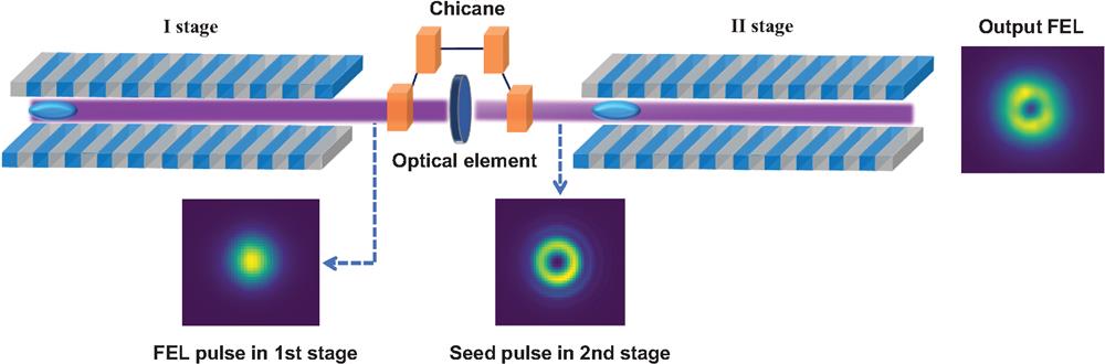
The schematic layout of the proposed method, referred to as self-seeded FEL with OAM (SSOAM), is shown in Fig. 1. Several undulator segments are employed as the first stage to generate an SASE FEL pulse in the linear regime. Then, an optical element, such as an SPP or SZP, is used to imprint the helical phase of a low-order OAM mode onto the FEL beam, generating an OAM seed pulse. Finally, the OAM seed pulse is significantly amplified in the second-stage undulator. A small magnetic chicane located between the first stage and the second stage is needed to detour the electron bunch, removing the microbunching introduced in the first stage, and resulting in a small delay below ten femtoseconds between the OAM seed and the electron bunch. Therefore, a relatively long electron bunch is requested in this scheme to ensure the amplification of the OAM seed in the second stage. In addition, fresh slice45 or twin bunch operation46 can also be employed to obtain better performance. The drift section between the first stage and the optical element can be increased to make the transverse size of the FEL pulses hitting the optics larger, which further reduces the impinging intensity and therefore minimizes heat-loading effects. In this case, utilizing an SZP or additional focusing optics may be necessary before entering the second stage.
Figure 1.Schematic layout of the self-seeded FEL with OAM.
Previous theoretical analyses indicated that an OAM seed can be amplified by the FEL process.47,48 In the SSOAM scheme, however, the SASE pulse filtered by the optical element is not a pure OAM pulse. We can theoretically analyze how FEL modes evolve in this scheme. First, we expand the slowly varying envelope of the electric field in the frequency domain into a Fourier series in the azimuthal angle according to Ref. 49, Where and are the longitudinal and transverse coordinates with respect to the undulator axis. indicates the topological charge. Each of the azimuthal harmonics is then decomposed into “self-reproducing” modes, with and . and are normalized versions of and according to the definition in Ref. 49, where is the gain parameter. and are eigenvalues and eigenfunctions of the guiding modes, respectively. Assuming no changes in the transverse profile and typical dimension of the electron beam, and the same gain parameter during the entire process, the normalization parameters will remain constant during all the steps, and the FEL eigenmodes obey the eigenvalue equation 49, where we recognize that is the Bessel differential operator. Here, is a function of and defined in Ref. 49 and .
Instead, during free-space propagation, the azimuthal harmonics of the electric field do not evolve in self-reproducing modes. Since after expansion in azimuthal harmonics, we have
In the first stage, we have a first azimuthal series of FEL modes satisfying Eq. (3). The modes evolve in free space before filtering. For simplicity, here we assume that filtering happens directly at the exit of the first undulator. The filtering amounts to a change in the phase. A phase of is introduced to the radiation field, which is a reasonable assumption when using a finely stepped phase plate. We can therefore write the filtered self-reproducing modes as .
The modes need now to be propagated in free space for a distance . We call with the free-space propagated version of , which obeys
Solving this equation for a propagation distance , we obtain
Performing first the integral over the phase, we find
To summarize, the field at the entrance of the second stage amounts to where indicates the normalized position in the first stage. One may approximate as fixed because we assume good mode selection in the first stage. Then, the contribution to the field at the entrance of the second stage can be approximated to
All the contributions for all values of will enter the second stage with a topological charge .
Now, the FEL eigenmodes in the second stage obey and we can decompose
Since the orbital momentum should be conserved, each of the components carries a fraction of the total OAM with topological charge . Each mode will be amplified at different rates for different values of . Assuming good mode selection, the mode for will be dominant for the topological charge . However, all the FEL modes with fixed and different will contribute to an OAM field distribution with the same topological charge given as where indicates the normalized position in the second stage. In this sense, these modes will not be in competition. The competition will come from modes with different topological charges.
The contribution for corresponds to the fundamental FEL mode and will be dominant in the first stage. As a result, the seed pulse in the second stage is mainly composed of the mode. In particular, the component of the mode of the seed pulse is transformed from the mode in the first stage. Therefore, it is important for the proposed method to properly optimize the undulator settings of both stages to ensure a good amplification of the mode at the second stage.
3 Results
To further illustrate the proposed scheme, a detailed example based on the parameters of European XFEL23 is studied with GENESIS50 simulations. A 14 GeV electron beam with a normalized emittance of 0.5 mm.mrad, a bunch length of 20 fs, and a current flattop profile of 5000 A is assumed here to produce nine keV FEL pulses. The electron beam is sent to the first stage and generates SASE pulses with energies of a few microjoules or less. Then, an SPP is used to impart a helical phase of , corresponding to , on the SASE pulse. We assume the intensity of the pulse is unchanged by the SPP. The distance between the SPP and both undulator sections is set to 2 m. For simplicity, the SASE pulse interacts with a fresh electron beam with an unchanged bunch length in the second stage.
As indicated by the theoretical analysis, the mode of the SASE pulse is transformed to the OAM mode while the the mode is transformed to the mode after the filtering. Therefore, the resonance and taper of the first stage undulator need to be optimized to achieve the largest possible ratio of the mode while keeping the pulse energy small. Meanwhile, the undulator of the second stage needs to be optimized to achieve the strongest possible amplification of the mode.
In the simulation, nine undulator segments with a length of 5 m and a 40 mm period are employed as the first stage. The optimization of the first-stage undulator suggests a slight reverse taper with . In this case, an SASE pulse with a pulse energy of is obtained at the end of the first stage. The mode decomposition of the pulse shows that the relative weight of the , , and modes are 91%, 3%, and 3%, respectively. The temporal power profile and transverse profile of the pulse are shown in Figs. 2(a) and 2(b), respectively. The FEL pulse is then propagated sequentially through the free-space section, the SPP, and the second free-space section, before being amplified as a seed in the second stage. As shown in Figs. 2(c) and 2(d), the seed pulse mainly consists of the mode, with a ratio of 91%. The ratio of the mode of the seed pulse is 3%.
Figure 2.Temporal power of the FEL pulse at (a) the end of the first stage and (c) the entrance of the second stage decomposed into OAM modes. The corresponding transverse profiles of the pulse at these two positions are shown in (b) and (d), respectively.
The OAM seed pulse is amplified in the second stage, which consists of seven undulator segments. To ensure optimal gain for the mode, the undulator taper is optimized to a strength of . The gain curves of pulse and different OAM modes are shown in Fig. 3. The pulse energy reaches at the end of the undulator. The modes and , which transform from and in the first stage, respectively, have similar initial components in the second stage but grow at very different rates. At the exit of the second stage, the mode is amplified 43.5-fold and approaches saturation. The ratio of the mode is first increased to 95% and then slowly decreased to 88%. The ratio of the mode reaches 9% at the end of the second stage. Figures 4(a) and 4(b) show the transverse profiles of the pulse at the exit of the fifth undulator cell, where the pulse energy is and the ratio of the mode is 93%, and the end of the seventh cell, respectively. Figure 4(c) presents the transverse phase distribution at the position in the pulse with a peak power of 92 GW, located at in Fig. 4(d).
Figure 3.Gain curves of different OAM modes along the second stage.
Figure 4.Transverse profile of the FEL pulse at the end of (a) the fifth cell and (b) the second stage. (c) Transverse phase distribution at the position of maximum power in the pulse. (d) Temporal power profile of the pulse at the end of the second stage.
Figure 5(a) presents the variation of the different OAM modes contained in the FEL pulse at the exit of the fifth undulator cell of the second stage as the total phase shift, i.e. , imprinted by the SPP changes. The results show that the proposed scheme can tolerate relatively large phase shift variations due to imperfections in optical element fabrication or changes in photon energy. With the introduction of phase shifts from to , corresponding to to , pulses with mode ratio exceeding 80% can be obtained. Moreover, the results also indicate that the proposed method can be used to effectively amplify the mode. FEL pulses with 84% of mode and pulse energy of can be obtained when the introduced phase shift is . High-order OAM modes with topological charge larger than 2 cannot be well amplified due to stronger diffraction.36,47
Figure 5.(a) Variation of the different OAM modes with the change of the imprinted total phase shift. (b) Gain curves of different OAM modes at the second stage starting from a weaker seed pulse.
To simulate the effects of a weaker seed power, we assume that the use of an optical element still introduces into the SASE pulse but with an efficiency of only 10%, while the undulator settings remain unchanged. In comparison to Fig. 2(c), the pulse energy of this seed pulse is reduced to . As shown in Fig. 5(b), the mode can be amplified 107-fold in the second stage even if it starts with a much weaker seed pulse. At the exit of the seventh undulator cell, the pulse energy reaches , where the ratios of the and modes are 87% and 9%, respectively. The FEL pulse can be further amplified to when nine undulator cells are employed. In this case, the ratios of the and modes are 78% and 17%, respectively.
4 Conclusion
We proposed a scheme to produce high-intensity short-wavelength vortices. Theoretical analysis and simulations demonstrate that the introduction of an OAM mode to an FEL beam using an optical element leads to changes in multiple transverse modes of the FEL beam, where the dominant OAM mode can be amplified by more than two orders of magnitude. Since the SSOAM scheme is based on the SASE operation, it can be enabled in a wide range of wavelengths, including extreme ultraviolet, soft, and hard X-rays. In combination with the self-seeding scheme, introducing OAM to a weak and monochromatic seed pulse and further amplifying it, narrow bandwidth X-ray vortices can be generated. The proposed method paves the way for the realization of high-power and high-repetition-rate X-ray vortices and promises to open up new ways for probing matter with such light, such as time-resolved twisted X-ray diffraction techniques.51
Jiawei Yan is a physicist at the European XFEL. He received his PhD from the Shanghai Institute of Applied Physics of the Chinese Academy of Sciences in 2021. His current research interests include free-electron laser physics, accelerator physics, and machine learning. His research work was awarded as one of China’s Top 10 Optical Breakthroughs (2021). He won the Excellent Doctoral Dissertation Award from the Chinese Academy of Sciences and the Young Investigator FEL Prize.
Gianluca Geloni is a physicist at the European XFEL. His interests are at the interface between electron accelerators and radiation generation by ultrarelativistic beams. He studied at Università di Genova (Italy) and he received his doctorate in physics from the Technische Universiteit Eindhoven (The Netherlands) in 2003. He spent the following years working at DESY, HASYLAB (Germany), and in 2010 he joined the European XFEL (Germany), where he became leader of the FEL Physics group and co-coordinator of the FEL R&D group. He currently focuses his research activity on the inception, assessment, and development of advanced FEL schemes.