
Peng Wang, Chi-Bing Shen. Mixing enhancement for supersonic mixing layer by using plasma synthetic jet [J]. Acta Physica Sinica, 2019, 68(17): 174701-1
- Acta Physica Sinica
- Vol. 68, Issue 17, 174701-1 (2019)
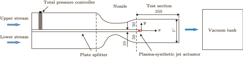
Fig. 1. Schematic of the supersonic mixing layer wind tunnel.超声速混合层风洞示意图
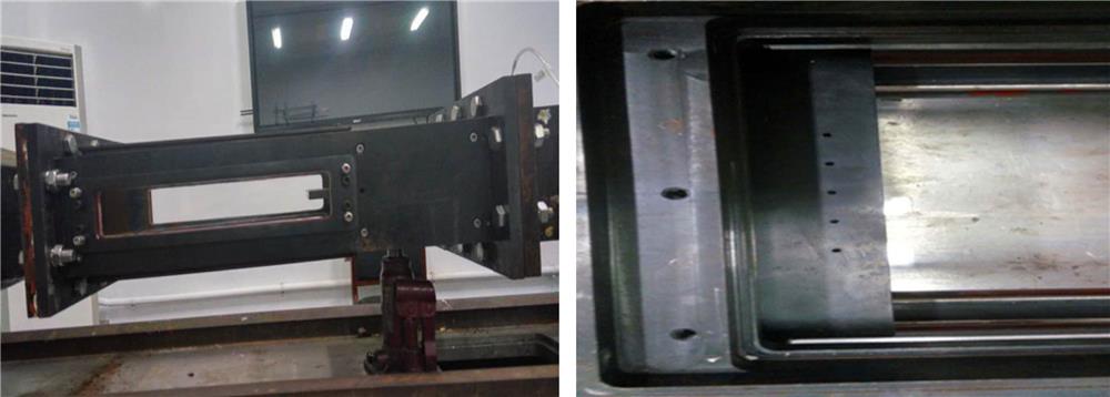
Fig. 2. The test section of supersonic mixing layer wind tunnel.超声速混合层风洞实物图
Fig. 3. Schematic of the wind tunnel and the actuator mounted inside a plate: (a) Splitter plate in the wind tunnel; (b) actuator in the splitter plate.安装有等离子体合成射流激励器隔板在风洞中的位置 (a) 隔板在风洞中位置; (b) 激励器在隔板上的位置
Fig. 4. Two-electrode plasma synthetic actuator两电极等离子体合成射流激励器
Fig. 5. The schematic diagram of schlieren system纹影系统示意图
Fig. 6. Schematics of the experimental system sequence chart.等离子体合成射流试验系统的时序示意图
Fig. 7. Schlieren images: (a) T 0 + 0 μs; (b) T 0 + 67 μs; (c) T 0 + 233 μs.
纹影结果 (a) T 0 + 0 μs; (b) T 0 + 67 μs; (c) T 0 + 233 μs
Fig. 8. NPLS images of supersonic mixing layer under perturbation and unperturbation: (a) Unperturbation; (b) T 0 + 180 μs; (c) T 0 + 230 μs.
等离子体合成射流对超声速混层作用的NPLS结果 (a) 未受扰动; (b) T 0 + 180 μs; (c) T 0 + 230 μs
Fig. 9. PIV experimental results: (a) Averaged X -velocity; (b) averaged X -velocity at T 0 + 230 μs; (c) Y -velocity standard deviation; (d) Y -velocity standard deviation at T 0 + 230 μs.
PIV的实验结果 (a) 流向速度的平均结果; (b) T 0 + 230 μs时刻流向速度的平均结果; (c) 横向速度标准差; (d) T 0 + 230 μs时刻横向速度标准差
Fig. 10. Physical model: (a) Unperturbation; (b) the actuator at the upper surface of the splitter plate; (c) the actuator at the end surface of splitter plate; (d) the actuator at bottom surface of splitter plate.仿真物理模型 (a) 无扰动; (b) 激励器在隔板上表面; (c) 激励器在隔板尾端; (d) 激励器在隔板下表面
Fig. 11. Calculation model and grid for code validation.算例验证的计算模型及网格
Fig. 12. Certification of grid independence and code validation网格无关性及算例验证
Fig. 13. T 0 + 67 μs, numerical and experimental schlierens: (a) Experimental schlieren; (b) numerical schlieren.
(T 0 + 67 μs)时刻纹影实验结果与数值纹影结果对比 (a) 纹影实验结果; (b) 数值纹影结果
Fig. 14. T 0 + 180 μs, contour of density and NPLS result: (a) NPLS result; (b) contour of density.
(T 0 + 180 μs)时刻NPLS结果与数值仿真密度场对比 (a) NPLS结果; (b) 数值仿真密度场
Fig. 15. Contours of density at T 0 + 555 μs: (a) Unperturbation; (b) the actuator at the upper surface of the splitter plate; (c) the actuator at the end surface of the splitter plate; (d) the actuator at the bottom surface of the splitter plate.
(T 0 + 555 μs)时刻密度场 (a) 未受扰动; (b) 激励器在隔板上表面; (c) 激励器在隔板尾端; (d) 激励器在隔板下表面
Fig. 16. Simulation of the temperature and flow: (a) The actuator at the upper surface of the splitter plate; (b) the actuator at the end surface of the splitter plate(T 0 + 75 μs)时刻温度云图和流线 (a) 激励器在隔板上表面; (b) 激励器在隔板尾端
Fig. 17. Time-averaged velocity thickness of mixing layer时均速度混合层厚度
Fig. 18. The parameters of actuator outlet: (a) The mass flow rate of actuator outlet; (b) the velocity of actuator outlet; (c) the momentum rate of actuator outlet; (d) the pressure of actuator outlet.激励器出口参数 (a) 激励器出口质量流量; (b) 激励器出口速度; (c) 激励器出口动量率; (d) 激励器出口压力
Fig. 19. Parameters of actuator cavity: (a) Density of the gas in the actuator chamber; (b) temperature of the gas in the actuator chamber; (c) pressure of the gas in the actuator chamber.激励器腔体内参数 (a) 激励器腔体密度; (b) 激励器腔体内温度; (c) 激励器腔体内压力
|
Table 1.
Flow parameters of supersonic mixing layer.
压力匹配情况下校测流场参数

Set citation alerts for the article
Please enter your email address
© Copyright 2018-2021 | Chinese Laser Press. All Rights Reserved 沪ICP备15018463号-20