• Acta Physica Sinica
  • Vol. 69, Issue 3, 034102-1 (2020)
Guang-Zhao Zhou1, Zhe Hu1、2、3, Shu-Min Yang1, Ke-Liang Liao4, Ping Zhou1, Ke Liu1, Wen-Qiang Hua1、*, Yu-Zhu Wang1、*, Feng-Gang Bian1, and Jie Wang1
Author Affiliations
  • 1Shanghai Synchrotron Radiation Facility, Zhangjiang Laboratory, Shanghai Advanced Research Institute, Chinese Academy of Sciences, Shanghai 201204, China
  • 2Shanghai Institute of Applied Physics, Chinese Academy of Sciences, Shanghai 201800, China
  • 3University of Chinese Academy of Sciences, Beijing 100049, China
  • 4Beijing Synchrotron Radiation Facility, Institute of High Energy Physics, Chinese Academy of Sciences, Beijing 100049, China
  • show less
    DOI: 10.7498/aps.69.20191586 Cite this Article
    Guang-Zhao Zhou, Zhe Hu, Shu-Min Yang, Ke-Liang Liao, Ping Zhou, Ke Liu, Wen-Qiang Hua, Yu-Zhu Wang, Feng-Gang Bian, Jie Wang. Preliminary exploration of hard X-ray coherent diffraction imaging method at SSRF[J]. Acta Physica Sinica, 2020, 69(3): 034102-1 Copy Citation Text show less
    Calculated (a) energy and (b) brilliance for odd harmonics as a function of the undulator K-value (a target ring current of 300 mA is used).储存环流强为300 mA时, 不同波荡器K值下, 计算得到不同奇次谐波的(a)能量和(b)亮度分布
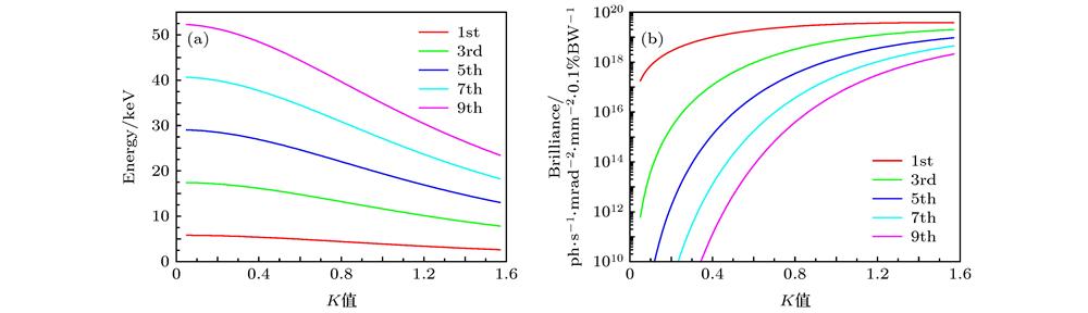
    Fig. 1. Calculated (a) energy and (b) brilliance for odd harmonics as a function of the undulator K-value (a target ring current of 300 mA is used). 储存环流强为300 mA时, 不同波荡器K值下, 计算得到不同奇次谐波的(a)能量和(b)亮度分布
    Beamline layout of the coherent scattering experimental modes on BL19U2: (a) Side view, vertical direction; (b) top view, horizontal direction.相干衍射实验模式@BL19U2光束线站布局图 (a)侧视图, 垂直方向; (b)上视图, 水平方向
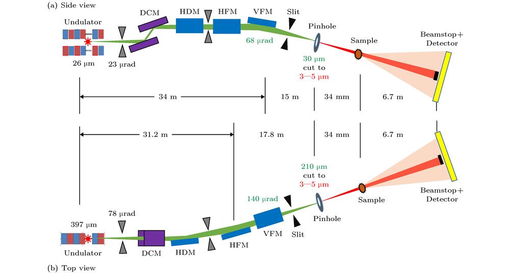
    Fig. 2. Beamline layout of the coherent scattering experimental modes on BL19U2: (a) Side view, vertical direction; (b) top view, horizontal direction.相干衍射实验模式@BL19U2光束线站布局图 (a)侧视图, 垂直方向; (b)上视图, 水平方向
    (a) Schematic diagram of experimental equipment; (b) on-site picture.(a)实验装置示意图; (b)现场照片
    Fig. 3. (a) Schematic diagram of experimental equipment; (b) on-site picture.(a)实验装置示意图; (b)现场照片
    (a), (b) Measured diffraction patterns of pinhole with incident beam of reduced coherence; diffracted intensity distribution in the horizontal (c) and vertical (d) direction along the dotted line profile in panel (a) and (b), and the intensity distribution are shown in log scale.(a), (b)不同入射光束相干度下的针孔衍射图样; (c)水平和(d)垂直方向上的衍射强度分布(图(a), (b)中白色虚线位置); 强度分布均为对数显示
    Fig. 4. (a), (b) Measured diffraction patterns of pinhole with incident beam of reduced coherence; diffracted intensity distribution in the horizontal (c) and vertical (d) direction along the dotted line profile in panel (a) and (b), and the intensity distribution are shown in log scale.(a), (b)不同入射光束相干度下的针孔衍射图样; (c)水平和(d)垂直方向上的衍射强度分布(图(a), (b)中白色虚线位置); 强度分布均为对数显示
    Coherent diffraction pattern (a), reconstruction (b) and SEM image (c) of pinhole.针孔样品的(a)相干衍射图, (b) 结构重建图, (c)扫描电镜图
    Fig. 5. Coherent diffraction pattern (a), reconstruction (b) and SEM image (c) of pinhole.针孔样品的(a)相干衍射图, (b) 结构重建图, (c)扫描电镜图
    (a) The 441st diffraction pattern collected by the detector; recovered (b) amplitude and (c) phase information of the sample structure of the Fresnel zone plate according to the diffraction patterns; (d) electron microscope image of the corresponding structures of the wave band specimens; reconstructed (e) amplitude and (f) phase information of the incident beam simultaneously according to the diffraction pattern.(a)探测器采集到的第441张衍射图; 根据衍射图重建波带片样品结构的(b)振幅和(c)相位信息; (d)波带片样品相应结构的电子显微镜图片; 根据衍射图重建的入射光束的(e)振幅和(f)相位信息
    Fig. 6. (a) The 441st diffraction pattern collected by the detector; recovered (b) amplitude and (c) phase information of the sample structure of the Fresnel zone plate according to the diffraction patterns; (d) electron microscope image of the corresponding structures of the wave band specimens; reconstructed (e) amplitude and (f) phase information of the incident beam simultaneously according to the diffraction pattern.(a)探测器采集到的第441张衍射图; 根据衍射图重建波带片样品结构的(b)振幅和(c)相位信息; (d)波带片样品相应结构的电子显微镜图片; 根据衍射图重建的入射光束的(e)振幅和(f)相位信息
    光束线站能量范围/keV光斑尺寸/μm相干通量相干实验方法
    NSLS 11-ID6—163—105 × 1011 ph/s@9.65 keV CoSAXS, XPCS
    PETRA-III P105—204.5—403 × 109 ph/s CDI, Bragg CDI, XPCS
    SPring-8 29 XUL4.5—18.7~1—20~109 ph/s CDI, Ptychography
    Diamond I13-16—351 × 1010 ph/s@8 keV CDI, Bragg CDI, Ptychography, XPCS
    APS 34-ID-C5—15~0.75 × 10⁹ ph/s@10 keV CoSAXS, Ptychography
    MAX IV CoSAXS4—2010 or 1001.5 × 1012 ph/s@10 keV CoSAXS, XPCS
    SLS X12 SA4.4—17.925 × 107 × 108 ph/s@6.2 keV CoSAXS
    PLS-II 9 C5—15< 3001.7 × 1010 ph/s@10 keV CDI, Bragg CDI, XPCS
    TPS 25 A5.5—201—101 × 1010 ph/s@6 keV CDI, XPCS
    Table 1. Well-known coherent scattering beamlines in the world.
    光子能量/ keV 谐波阶数磁场/TK亮度/ 1018flux·mm–2·mrad–2光通量/ 1014ph·s–1·0.1%BW–1相干光通量/ 109ph·s–1·0.1%BW–1
    830.8221.53519.54.43111
    1030.6541.22112.52.8044.9
    1230.5120.9556.261.3715.3
    13.550.8161.5238.641.6814.8
    1550.7341.3706.091.178.34
    Table 2. Photon energy and highest brilliance/flux/coherent flux with corresponding undulator parameters (a target ring current of 300 mA is used).
    水平方向垂直方向
    光源点光斑尺寸397 µm26 µm
    光源点发散度78 µrad23 µrad
    光源点相干长度0.48 µm1.29 µm
    光源点相干度0.15%7.59%
    KB镜处光斑尺寸1073 µm距离光源31.2 m434 µm距离光源点34 m
    KB镜处相干长度3.36 µm57.3 µm
    Table 3. Beam parameters of BL19U2 (@12 keV) at the source and KB mirrors.
    Guang-Zhao Zhou, Zhe Hu, Shu-Min Yang, Ke-Liang Liao, Ping Zhou, Ke Liu, Wen-Qiang Hua, Yu-Zhu Wang, Feng-Gang Bian, Jie Wang. Preliminary exploration of hard X-ray coherent diffraction imaging method at SSRF[J]. Acta Physica Sinica, 2020, 69(3): 034102-1
    Download Citation