• Chinese Optics Letters
  • Vol. 19, Issue 5, 050604 (2021)
Jiaming Lin1, Zihao Du1, Chuying Yu1, Wenmin Ge1, Weichao Lü1, Huan Deng1, Chao Zhang1, Xiao Chen1, Zejun Zhang1、2、3, and Jing Xu1、2、3、*
Author Affiliations
  • 1Optical Communications Laboratory, Ocean College, Zhejiang University, Zhoushan 316021, China
  • 2Key Laboratory of Ocean Observation-Imaging Testbed of Zhejiang Province, Ocean College, Zhejiang University, Zhoushan 316021, China
  • 3The Engineering Research Center of Oceanic Sensing Technology and Equipment, Ministry of Education, Zhejiang University, Zhoushan 316021, China
  • show less
    DOI: 10.3788/COL202119.050604 Cite this Article Set citation alerts
    Jiaming Lin, Zihao Du, Chuying Yu, Wenmin Ge, Weichao Lü, Huan Deng, Chao Zhang, Xiao Chen, Zejun Zhang, Jing Xu. Machine-vision-based acquisition, pointing, and tracking system for underwater wireless optical communications[J]. Chinese Optics Letters, 2021, 19(5): 050604 Copy Citation Text show less
    Structure diagram showing an example of how to combine the existing UWOC system with the proposed APT system.
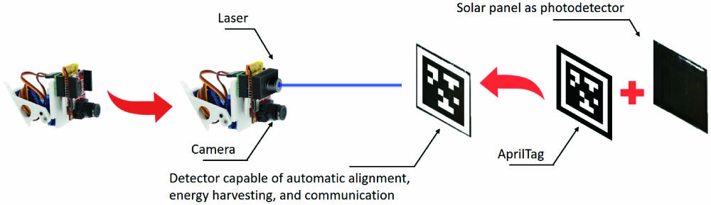
    Fig. 1. Structure diagram showing an example of how to combine the existing UWOC system with the proposed APT system.
    Experimental setup of the proposed APT system for UWOC. Insets: (a) the camera with servos, (b) the water tank, and (c) the AprilTag36H11-2.
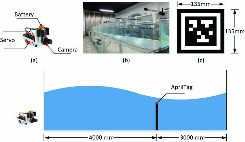
    Fig. 2. Experimental setup of the proposed APT system for UWOC. Insets: (a) the camera with servos, (b) the water tank, and (c) the AprilTag36H11-2.
    Influence of different factors on the pointing time showing (a) the pointing time of the proposed APT system measured in the underwater channel at different distances and (b) the pointing time of the proposed APT system measured in the underwater channel at different illuminations.
    Fig. 3. Influence of different factors on the pointing time showing (a) the pointing time of the proposed APT system measured in the underwater channel at different distances and (b) the pointing time of the proposed APT system measured in the underwater channel at different illuminations.
    Schematic diagram of roll angle, yaw angle, and pitch angle.
    Fig. 4. Schematic diagram of roll angle, yaw angle, and pitch angle.
    Pointing time of the proposed APT system measured in the underwater channel at different roll angles.
    Fig. 5. Pointing time of the proposed APT system measured in the underwater channel at different roll angles.
    Pointing time of the proposed APT system measured in the underwater channel (a) for different yaw angles and (b) for different pitch angles.
    Fig. 6. Pointing time of the proposed APT system measured in the underwater channel (a) for different yaw angles and (b) for different pitch angles.
    Pointing time of the proposed APT system measured in the underwater channel with different scintillations.
    Fig. 7. Pointing time of the proposed APT system measured in the underwater channel with different scintillations.
    Influence of different factors on the tracking/acquisition time showing (a) the tracking time of the proposed APT system measured in a 5 m air channel at different speeds and (b) the acquisition time of the proposed APT system measured in a 3 m air channel at different angles.
    Fig. 8. Influence of different factors on the tracking/acquisition time showing (a) the tracking time of the proposed APT system measured in a 5 m air channel at different speeds and (b) the acquisition time of the proposed APT system measured in a 3 m air channel at different angles.
    (a) A schematic diagram of the APT system acquiring a target and (b) the experimental setup for the acquisition time measurement at different deviation angles (α). The yellow area is the camera’s field of view, and the green line is the optical axis of the APT system.
    Fig. 9. (a) A schematic diagram of the APT system acquiring a target and (b) the experimental setup for the acquisition time measurement at different deviation angles (α). The yellow area is the camera’s field of view, and the green line is the optical axis of the APT system.
    Experimental setup for proof-of-concept experiments for the proposed APT system integrated into a UWOC system.
    Fig. 10. Experimental setup for proof-of-concept experiments for the proposed APT system integrated into a UWOC system.
    (a) Eye diagrams of the integrated system using NRZ-OOK modulation after acquiring the target through a 285 mm water channel, and (b) the pointing time of the proposed APT system measured in the underwater channel with different magnesium hydroxide powder concentrations.
    Fig. 11. (a) Eye diagrams of the integrated system using NRZ-OOK modulation after acquiring the target through a 285 mm water channel, and (b) the pointing time of the proposed APT system measured in the underwater channel with different magnesium hydroxide powder concentrations.
    Eye diagrams of the integrated system using NRZ-OOK modulation during tracking the target through a 285 mm air channel.
    Fig. 12. Eye diagrams of the integrated system using NRZ-OOK modulation during tracking the target through a 285 mm air channel.
    Jiaming Lin, Zihao Du, Chuying Yu, Wenmin Ge, Weichao Lü, Huan Deng, Chao Zhang, Xiao Chen, Zejun Zhang, Jing Xu. Machine-vision-based acquisition, pointing, and tracking system for underwater wireless optical communications[J]. Chinese Optics Letters, 2021, 19(5): 050604
    Download Citation