Abstract
A frequency-tunable wireless access scheme based on optoelectronic oscillating technology is proposed and experimentally demonstrated. By using this scheme, the frequency of the transmitted wireless signals can be tuned by adjusting the wavelength of the input light. The 1.25 Gb/s on-off keying signals with the carrier frequency of 8–14.5 GHz are generated and transmitted through a radio over fiber link. The envelope detecting technique is employed in the receiver to support the down-conversion and demodulation. Electrical local oscillators are not required in the transmitter and receiver end, which simplifies the system structure and lowers the cost.The rapid growth of the demands for transmission bandwidth becomes a significant issue in a wireless access network[1]. Radio over fiber (RoF) technology is one of the most promising ways to break the bandwidth bottleneck due to the advantages of low loss, large bandwidth, and low cost[2–8].
Many RoF schemes have been reported to provide stable wireless access, most of which contribute to improving spectral efficiency, canceling phase noise, decreasing the nonlinearization distortion, and ameliorating digital signal processing (DSP) at the receiver[5–8]. However, in these structures, a local oscillator (LO) is usually required at the transmitter to provide carrier signals with high frequency. Moreover, an LO is also needed at the receiver end for signal down-conversion. Consequently, the electromagnetic immunity of the whole system is degraded due to the high frequency part, and the system is not cost-effective. On the other hand, these schemes can only provide a fixed-frequency wireless access, which cannot provide frequency tunability according to different wireless scenery.
The optoelectronic oscillator (OEO) has been considered one of the most effective photonic applications in the microwave domain, such as wireless communications, radar, modern instrumentation, microwave imaging, and microwave spectroscopy[9–12]. Microwave signals with high frequency and ultra-low phase noise can be obtained using an OEO[12–15]. Moreover, the frequency of the obtained microwave signals can be tuned by adjusting the input optical wavelength in some OEO structures[14], which makes it possible to provide multiple services with different frequencies. In addition, the frequency tunability of a wireless access network provides a possibility to evade the congested frequency band, according to the network condition in time.
Sign up for Chinese Optics Letters TOC. Get the latest issue of Chinese Optics Letters delivered right to you!Sign up now
In this Letter, a frequency-tunable wireless access transmission system based on the OEO technique is proposed and experimentally demonstrated. A tunable microwave photonic filter (MPF) using a phase-shifted fiber Bragg grating (PS-FBG) is employed in the OEO to provide the frequency tunability, which is achieved by adjusting the input optical wavelength. A broadband LO is not required at the wireless receiver end as envelope detecting is used for the signal down-conversion. Only one radio access unit in the user end (UE) is capable of providing different access frequencies, which simplifies the system structure and lowers the cost. The 1.25 Gb/s on-off keying (OOK) signals with the carrier frequencies of 8–14.5 GHz are generated and transmitted through a RoF link.
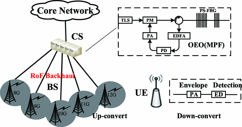
The conceptual diagram of the proposed frequency-tunable RoF system is shown in Fig. 1. In order to simulate the communication between a central station (CS) and a user, the system diagram is present with three parts, including the CS, base station (BS), and UE. The OEO is employed in the CS to provide carrier signals with tunable frequencies, which contains a tunable MPF using a PS-FBG. The BS only consists of a photodetector (PD), a wideband low noise amplifier, and a high gain antenna. In the UE, only one radio access unit is applied.

Figure 1.Conceptual diagram of the proposed frequency-tunable RoF system.
The schematic of the MPF is shown in the insert of Fig. 1. The MPF contains a tunable laser source (TLS), a phase modulator (PM), a PS-FBG, an erbium-doped fiber amplifier (EDFA), a PD, and a microwave power amplifier (PA). A light source from the TLS is sent to the PM, which is driven by feedback microwave signals. Under the condition of small signals modulation, the power of the second order and the higher order sidebands is much smaller than that of the carrier and the first sidebands. Therefore, the signals at the output of the PM only contain an optical carrier and two first sidebands, neglecting the higher sidebands. As the phase difference is between the two first sidebands, the received signals at the PD cancel each other out, which results in a direct current part. Then, the phase-modulated signals are sent to the PS-FBG via the optical circulator. The reflected spectrum of PS-FBG used in our experiment is schematically shown in Fig. 2(a), which has two ultra-narrow notches with fast phase variations. When one sideband of the phase-modulated light wave is placed in the notch of the PS-FBG, the amplitude and the phase of the sideband is varied[15]. The reflected signals will contain the optical carrier and another sideband. Then, microwave signals are obtained through frequency beating at the PD, which achieves the conversion from phase-modulated signals to intensity-modulated signals[16,17]. When we change the wavelength of the incident light wave from to , the difference between the optical carrier and the notch would be varied. Then, we can get the microwave signal with different frequencies and . The frequency response of the MPF is also shown in Fig. 2(b). Consequently, a tunable MPF can be achieved by tuning the wavelength of the incident light wave.
Figure 2.(a) Illustration of the operation of the MPF and (b) the MPF frequency response.
Combined with the characteristics of the tunable MPF and the beating of reflected signals in PS-FBG, a widely tunable OEO loop can be achieved. The oscillating frequency is equal to the frequency spacing between the notch and the incident light source. In this configuration, the generated signals frequency can be tuned by adjusting the wavelength of the incident light wave. In addition, the optical sideband at the filter notch can be used as a light source to carry transmitted data. After transmission through a fiber link, the optical signals are transferred into the microwave domain by frequency beating of the optical carrier and the modulated sideband at the PD. Then, a horn antenna with the bandwidth from 7 to 15 GHz is employed to transmit the radio frequency (RF) signals. Wireless applications with different frequencies can be provided by using this system. At the UE, the received RF signals are amplified and demodulated. Envelope detection is implemented to convert the RF signals to the baseband, which substitutes the coherent demodulation method and makes the system more cost-effective.
The frequency response of the proposed filter is measured by a vector network analysis (VNA, Anritsu MS4645B), as Fig. 3 shows. A microwave sinusoidal signal from the VNA is applied to the PM, scanning from 1 to 15 GHz. The wavelength of the incident optical source is set at 1552.53 nm, which is closer to the right notch in the reflected spectrum of the PS-FBG. Therefore, the upper sideband is placed in the notch of the PS-FBG when the microwave frequency is equal to the difference between the frequency of the optical carrier and the center frequency of the notch. By decreasing the wavelength of the optical carrier, the center frequency of the MPF is increased. Figure 4 shows the superimposed frequency responses of the MPF with the central frequency tuned from 1 to 15 GHz, while the tuning step of the incident light wavelength is 0.01 nm. It can be seen from Fig. 4 that the ratio of the transmission peak to the side lobe can reach 30 dB, which is large enough to suppress the undesired modes in the OEO. Moreover, it provides a new solution to provide tunable frequency using in the RoF system.
Figure 3.Schematic of the wideband frequency-tunable MPF. PC, polarization controller; OC, optical coupler.
Figure 4.(Color online) Superimposed frequency responses of the MPF.
The experimental diagram of the proposed frequency-tunable RoF system is shown in Fig. 5. The wavelength of the laser launched into the PM is set at 1552.55 nm. The modulated light passes into the PS-FBG. By adjusting the EDFA, the OEO loop can be closed. The higher sideband will fall into the notch of the PS-FBG when the microwave frequency is equal to the difference between the frequency of the optical carrier and the center frequency of the notch. Figure 6 shows the reflective function of the PS-FBG and the relative location of the optical carrier and the first sideband. The location of the notch is about 1552.62 nm, which is equal to the center frequency of the st sideband, as Fig. 6(b) shows. The difference between the optical carrier and notch is about 0.07 nm. Then, the reflected optical carrier and lower sideband are sent to an EDFA and an optical coupler and beaten into the PD, generating 8.75 GHz RF signals. The generated RF signals are boosted by the PA proving sufficient gain, forming the OEO loop. By changing the wavelength of the optical carrier, the frequency of the generated microwave signals can be tuned. As the results show in Fig. 7, electrical signals centered at 8–14.5 GHz are generated by changing the wavelength of the TLS, verifying the frequency tunability of the proposed scheme. By maintaining the stability of the OEO ring, high-quality tunable microwave signals can be obtained.
Figure 5.Experimental diagram of the proposed frequency-tunable RoF system.
Figure 6.(a) Reflected and (b) transmitted spectrum of the PS-FBG.
Figure 7.(Color online) Generated microwave signals with different frequencies.
Moreover, the transmitted optical sideband is modulated by the 1.25 Gbps signals from a pseudorandom pattern generator (PPG) via a Mach–Zehnder modulator (MZM). Then, the modulated signals and the reflected signals are combined by an optical coupler and transmitted to the receiver terminal through a 10 km fiber. When the wavelength of the TLS is set at 1552.545 nm, the frequency beating between the optical carrier and sideband can generate microwave signals with the frequency of 9.38 GHz. Figure 8 shows the spectrum of the generated microwave signals at the output of PD2. Then, a horn antenna transmits the signals into the space after it is amplified by the PA. Meanwhile, the antenna also can act as a band-pass electrical filter, cutting off the signals that are out of the frequency range. Finally, the envelope detecting technique is used to demodulate the received signals.
Figure 8.Spectrum of the generated RF signals at PD2.
Figure 9(a) shows the spectrum of the demodulated baseband signals in a back-to-back (BTB) transmission, while the optical power launched into PD2 is 2 dBm. When we set the power launched into PD2 as 0 dBm after a 10 km fiber transmission, the spectrum of the received baseband signals is shown in Fig. 9(b). The bit error rate (BER) performance for the signals data after transmission through a single mode fiber (SMF) of 0 and 10 km are also evaluated, which is shown in Fig. 10. The insert (a) of Fig. 10 shows the eye diagram at the BER of in a BTB transmission. The insert (b) of Fig. 10 shows the eye diagram when the BER is after a 10 km fiber transmission. The BER curves and eye diagrams demonstrate the feasibility of the proposed system.
Figure 9.Spectrum of the received baseband signals: (a) BTB with the received optical power of 2 dBm, (b) 10 km with the received optical power of 0 dBm.
Figure 10.BER curves and the eye diagrams of the signals at different transmission distances BTB and 10 km.
The tunability of the proposed structure is verified by changing the wavelength of the TLS. By this way, electrical LOs are not required in the transmitter and receiver end. Actually, in practical applications, the wireless network condition is generally dynamic; hence, a separate uplink for the end users to provide emergency feedback to the central office, enabling a rapid switch of the transmission frequency band according to the specific scenarios, is essential for the proposed system. Therefore, a symmetric bidirectional transmission system should be discussed in future work.
In conclusion, a frequency-tunable ROF system based on an OEO technique is proposed and experimentally demonstrated. By controlling the input optical wavelength, microwave signals with the frequencies from 8 to 14.5 GHz can be obtained at the transmitter. The 1.25 Gb/s OOK signals are modulated onto the microwave carrier and transmitted through an RoF transmission link. Eye diagrams and BER curves are present to verify the transmission system. The proposed scheme realizes a large frequency tunability, which makes it possible to select suitable transmission frequency bands according to the current wireless network condition.
References
[1] A. S. Gowda, A. R. Dhaini, L. G. Kazovsky, H. Yang, S. T. Abraha, A. Ng’oma. J. Lightwave Technol., 32, 3545(2014).
[2] Y. Fan, J. Li, Y. Lei, M. Tang, F. Yin, Y. Dai, K. Xu. Chin. Opt. Lett., 15, 010011(2017).
[3] C. Gao, S. Huang, J. Xiao, X. Gao, Q. Wang, Y. Wei, W. Zhai, W. Xu, W. Gu. Chin. Opt. Lett., 13, 010604(2015).
[4] D. Novak. J. Quantum Electron., 52, 1(2016).
[5] G.-K. Chang, C. Liu, L. Zhang. IEEE International Conference on Communications Workshops (ICC)(2013).
[6] X. Pang, A. Caballero, A. Dogadaev, V. Arlunno, R. Borkowski, J. S. Pedersen, X. Yu. Opt. Express, 19, 24944(2011).
[7] J. Yin, K. Xu, Y. Li, J. Wu, X. Hong, J. Lin. Proceedings of OFC(2009).
[8] P. T. Dat, A. Kanno, K. Inagaki, T. Kawanishi. J. Lightwave Technol., 32, 3910(2014).
[9] L. Maleki. Nat. Photon., 5, 728(2011).
[10] T. Berceli, P. R. Herczfeld. IEEE Trans. Microwave Theory Tech., 58, 2992(2010).
[11] X. Zou, X. Liu, W. Li, P. Li, W. Pan, L. Yan, L. Shao. IEEE J. Quantum Electron., 52, 1(2016).
[12] X. Liu, W. Pan, X. Zou, D. Zheng, L. Yan, B. Luo. IEEE Photon. J., 5, 6600606(2013).
[13] X. Xie, C. Zhang, T. Sun, P. Guo, X. Zhu, L. Zhu, W. Hu, Z. Chen. Opt. Lett., 38, 655(2013).
[14] W. Li, J. P. Yao. IEEE Trans. Microwave Theory Tech., 60, 1735(2012).
[15] S. Poinsot, H. Porte, J. P. Goedgebuer, W. T. Rhodes, B. Boussert. Opt. Lett., 27, 1300(2002).
[16] F. Zeng, J. P. Yao. J. Lightwave Technol., 23, 1721(2005).
[17] Y. Gao, A. Wen, L. Liu, S. Tian, S. Xiang, Y. Wang. J. Lightwave Technol., 33, 2899(2015).