
Yan YUAN, Anqi LIU, Lijuan SU. Development Trends and Prospects of Snapshot Spectral Imaging Technology(Invited)[J]. Acta Photonica Sinica, 2022, 51(7): 0751404
- Acta Photonica Sinica
- Vol. 51, Issue 7, 0751404 (2022)
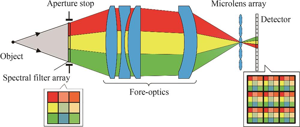
Fig. 1. Schematic of light field imaging spectroscopy
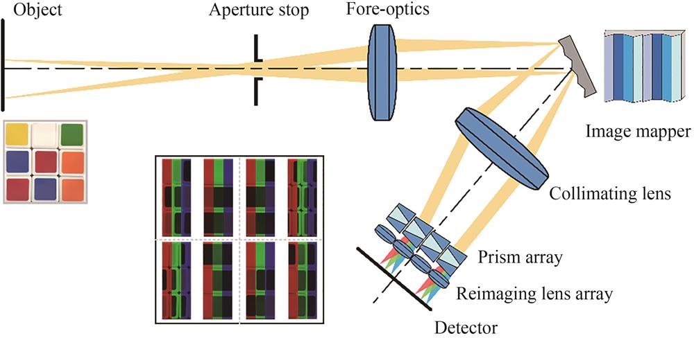
Fig. 2. Schematic of image mapping spectroscopy
Fig. 3. Schematic of coded aperture snapshot spectral imaging
Fig. 4. Schematic of snapshot hyperspectral imaging Fourier transform spectroscopy[23]
Fig. 5. Overview of the research status and development trend of snapshot spectral imaging technology
Fig. 6. Principle of the 3DIS system[34]
Fig. 7. Schematic of the snapshot hyperspectral light field imager[35]
Fig. 8. Schematic of the spectral-depth imaging system with high resolution[36]
Fig. 9. Photograph of the spectral-depth imaging system using structured light[37]
Fig. 10. Schematic of the snapshot hyperspectral volumetric microscopy based on camera array[38]
Fig. 11. Schematic of a snapshot hyperspectral light field imaging system using a single camera[40]
Fig. 12. Schematic of the snapshot spectral-volumetric imaging system based on Fourier transform[41]
Fig. 13. Schematic of the compressive spectral integral imaging system[42]
Fig. 14. Schematic of the snapshot spectral-volumetric imaging system using a ToF camera[43]
Fig. 15. Schematic of the coded aperture snapshot spectral depth imaging via depth from coded aberrations(CASSDI-DFA)[44]
Fig. 16. Schematic of the snapshot hyperspectral light field tomography[45]
Fig. 17. Schematic of the snapshot hyperspectral-depth imaging system with diffractive optics[46]
Fig. 18. Schematic of high-resolution hyperspectral video acquisition with a hybrid camera system[54]
Fig. 19. Schematic of hybrid-resolution spectral video system[55]
Fig. 20. Schematic of the high-resolution panchromatic image acquisition method for SHIFT[57]
Fig. 21. Diagram of hyperspectral image super-resolution based on SRCNN[64]
Fig. 22. Diagram of hyperspectral image super-resolution based on SDCNN and SCT[65]
Fig. 23. Result of spectral image super-resolution[67]
Fig. 24. Diagram of the joint artifact correction and super-resolution network
|
Table 1. Comparison of different snapshot spectral volumetric imaging technologies

Set citation alerts for the article
Please enter your email address
© Copyright 2018-2021 | Chinese Laser Press. All Rights Reserved 沪ICP备15018463号-20