• Chinese Journal of Lasers
  • Vol. 50, Issue 5, 0506004 (2023)
Kun Cheng1、2, Wentao Zhang1、3、*, Wenzhu Huang1、3, and Jianxiang Zhang1、2
Author Affiliations
  • 1State Key Laboratory of Transducer Technology, Institute of Semiconductors, Chinese Academy of Sciences,Beijing 100083, China
  • 2College of Materials Science and Opto-Electronic Technology, University of Chinese Academy of Sciences,Beijing 100049, China
  • 3Center of Materials Science and Optoelectronics Engineering, University of Chinese Academy of Sciences,Beijing 100049, China
  • show less
    DOI: 10.3788/CJL220842 Cite this Article Set citation alerts
    Kun Cheng, Wentao Zhang, Wenzhu Huang, Jianxiang Zhang. High‐Resolution Optical Fiber Time‐Division Multiplexing Static Strain Sensing Technology[J]. Chinese Journal of Lasers, 2023, 50(5): 0506004 Copy Citation Text show less
    Structural diagrams of interferometric fiber sensing time-division multiplexing system with experimental schemes of two different sets of sensor interferometers and reference interferometers shown in insets Ⅰ and Ⅱ
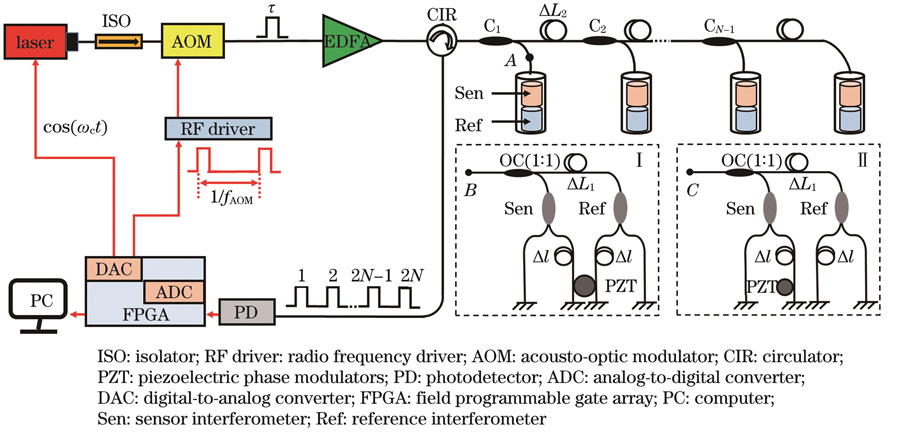
    Fig. 1. Structural diagrams of interferometric fiber sensing time-division multiplexing system with experimental schemes of two different sets of sensor interferometers and reference interferometers shown in insets Ⅰ and Ⅱ
    Flow chart of phase demodulation
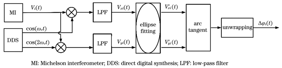
    Fig. 2. Flow chart of phase demodulation
    Sound and vibration isolation box. (a) Appearance of sound and vibration isolation box; (b) structural diagram of sound and vibration isolation box
    Fig. 3. Sound and vibration isolation box. (a) Appearance of sound and vibration isolation box; (b) structural diagram of sound and vibration isolation box
    Phase demodulation results before and after processing by ellipse fitting algorithm. (a) Before processing by ellipse fitting algorithm; (b) after processing by ellipse fitting algorithm
    Fig. 4. Phase demodulation results before and after processing by ellipse fitting algorithm. (a) Before processing by ellipse fitting algorithm; (b) after processing by ellipse fitting algorithm
    Results of sensor interferometer and reference interferometer before and after ellipse fitting. (a) Result of reference interferometer; (b) result of sensor interferometer
    Fig. 5. Results of sensor interferometer and reference interferometer before and after ellipse fitting. (a) Result of reference interferometer; (b) result of sensor interferometer
    Phase demodulation results of sensor interferometer and reference interferometer in one group.
    Fig. 6. Phase demodulation results of sensor interferometer and reference interferometer in one group.
    Phase demodulation results calculated by ellipse fitting method and reference compensation method. (a) Channel 1; (b) Channel 2; (c) Channel 3; (d) Channel 4
    Fig. 7. Phase demodulation results calculated by ellipse fitting method and reference compensation method. (a) Channel 1; (b) Channel 2; (c) Channel 3; (d) Channel 4
    Square wave signal with peak-peak value of 20 nε acting on sensing arm of sensor interferometer
    Fig. 8. Square wave signal with peak-peak value of 20 nε acting on sensing arm of sensor interferometer
    ReferenceStyle of sensorNumber of sensorsStrain resolution /nε
    25Fiber laser sensor10.248
    10Fiber laser sensor10.270
    11FBG-FP sensor10.670
    This paperFiber Michelson interferometer40.260
    Table 1. Performance comparison of optical fiber strain sensor system
    Kun Cheng, Wentao Zhang, Wenzhu Huang, Jianxiang Zhang. High‐Resolution Optical Fiber Time‐Division Multiplexing Static Strain Sensing Technology[J]. Chinese Journal of Lasers, 2023, 50(5): 0506004
    Download Citation