• Acta Photonica Sinica
  • Vol. 52, Issue 7, 0712002 (2023)
Jiali PENG1,2,3, Ping RUAN1,3,*, Youjin XIE1,3, Zhiguo LI1,3..., Jiahao WANG1,2,3 and Jingyu HAN1,2,3|Show fewer author(s)
Author Affiliations
  • 1Xi’an Institute of Optics and Precision Mechanics,Chinese Academy of Sciences,Xi'an 710119,China
  • 2University of Chinese Academy of Sciences,Beijing 100049,China
  • 3Key Laboratory of Space Precision Measurement Technology,Chinese Academy of Sciences,Xi'an 710119,China
  • show less
    DOI: 10.3788/gzxb20235207.0712002 Cite this Article
    Jiali PENG, Ping RUAN, Youjin XIE, Zhiguo LI, Jiahao WANG, Jingyu HAN. Dynamic Characteristics Analysis of Space Electro-optical Tracking and Pointing Turntable[J]. Acta Photonica Sinica, 2023, 52(7): 0712002 Copy Citation Text show less
    Overall structure of space electro-optical tracking and pointing turntable
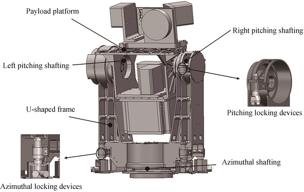
    Fig. 1. Overall structure of space electro-optical tracking and pointing turntable
    Mechanical model of the Bushing element
    Fig. 2. Mechanical model of the Bushing element
    Shafting structure design section
    Fig. 3. Shafting structure design section
    Relative displacement of inner-outer rings under the combined action of radial,axial and moment loads
    Fig. 4. Relative displacement of inner-outer rings under the combined action of radial,axial and moment loads
    Mechanical model of the locking devices
    Fig. 5. Mechanical model of the locking devices
    Bushing element of shafting
    Fig. 6. Bushing element of shafting
    Bushing element of locking devices
    Fig. 7. Bushing element of locking devices
    Finite element model of space electro-optical tracking and pointing turntable
    Fig. 8. Finite element model of space electro-optical tracking and pointing turntable
    Modal test of space electro-optical tracking and pointing turntable
    Fig. 9. Modal test of space electro-optical tracking and pointing turntable
    The first six mode shapes of modal test
    Fig. 10. The first six mode shapes of modal test
    The first six mode shapes by modal test
    Fig. 11. The first six mode shapes by modal test
    Measurement points in swept-sine vibration test
    Fig. 12. Measurement points in swept-sine vibration test
    0.2 g swept-sine vibration test curve
    Fig. 13. 0.2 g swept-sine vibration test curve
    The response curves comparison of test with simulation
    Fig. 14. The response curves comparison of test with simulation
    kx,y /(N·mm-1kz /(N·mm-1kθx,θy /(N·mm/°)kθz /(N·mm/°)
    Azimuth shafting2.5×1051.1×105--
    Left-pitching shafting1.6×10570 0005.1×107-
    Right-pitching shafting30 00030000
    Table 1. Bearing stiffness calculation results
    ModeNature frequency/HzModal shape
    144.1Rotate around pitching shafting
    266.5Swing back and forth
    367.4Swing left and right
    4106.7Rotate around azimuth shafting
    5174.8Local modal
    6186.5Swing up and down
    Table 2. The first six natural frequencies of modal test
    No.Working conditions
    Azimuth locking devicesPitching locking devices
    1UnlockedUnlocked
    2UnlockedLocked
    3LockedLocked
    Table 3. Modal test setting
    Mode shapeRotate around pitching shafting
    Working conditions1
    Test/Hz32.7
    Simulation/Hz33.5
    Relative error/%2.4
    Table 4. Stiffness identification of pitching shafting
    Mode shapeSwing left and rightSwing back and forthRotate around azimuth shafting
    Working conditions1
    Test/Hz42.45840.1
    Simulation/Hz4358.439.2
    Relative error/%1.40.62.2
    Table 5. Stiffness identification of azimuthal shafting
    Mode shapeSwing back and forthSwing left and rightRotate around pitching shafting
    Working conditions2
    Test/Hz61.246.640.6
    Simulation/Hz61.846.341.4
    Relative error/%0.90.61.9
    Table 6. Stiffness identification of pitching locking devices
    Mode shapeSwing left and rightSwing back and forthSwing up and down
    Working conditions3
    Test/Hz67.466.5186.5
    Simulation/Hz68.866.9184.8
    Relative error/%2.00.60.9
    Table 7. Stiffness identification of azimuth locking devices
    Stiffness
    kx /(N·mm-1ky /(N·mm-1kz /(N·mm-1kθx /(N·mm/°)kθy /(N·mm/°)kθz /(N·mm/°)
    Azimuth shafting2.5×1052.5×1051.1×1052.5×1074.5×1075.5×105
    Left-pitching shafting1.6×1051.6×10570 0005.1×1075.1×107105
    Rightt-pitching shafting30 00030 000300000
    Pitching locking devices50 00050 00030 0000107107
    Azimuth locking devices15 00015 00025 000000
    Table 8. The stiffness coefficient of each Bushing elements
    Modal shapeModal TestSimulation 1Simulation 2Simulation 3
    Nature frequency/Hz
    Rotate around pitching shafting44.144.743.434.7
    Swing back and forth66.567.985.173.4
    Swing left and right67.469.196.278.4
    Rotate around azimuth shafting106.7110.1135.4127.8
    Local modal174.8167.7190.4143.6
    Swing up and down186.5184.4368.9201.9
    Table 9. Comparison of nature frequency between simulation and modal test
    OrientationFrequency/HzVibration level(gTolerance
    X,Y,Z5~2000.2(4 oct·min-1

    ≤25 Hz,±0.5 Hz

    >25 Hz,±2%

    Table 10. Test condition of 0.2 g swept-sine vibration test
    ModeTest/HzSimulation/HzRelative error/%
    147.144.75.3
    269.967.92.8
    371.269.12.9
    4111.3110.11.1
    5165167.71.6
    6193.2184.44.6
    Table 11. 0.2 g swept-sine vibration test results and simulation errors
    OrientationMAX response pointModeTest response/gSimulation response/gRelative errors/%
    XA623.683.563.2
    YA134.394.380.2
    ZA863.193.093.1
    Table 12. Modal damping coefficient identification
    Jiali PENG, Ping RUAN, Youjin XIE, Zhiguo LI, Jiahao WANG, Jingyu HAN. Dynamic Characteristics Analysis of Space Electro-optical Tracking and Pointing Turntable[J]. Acta Photonica Sinica, 2023, 52(7): 0712002
    Download Citation