
Yuanzhi Dong, Yunxia Jin, Fanyu Kong, Jingyin Zhao, Jianwei Mo, Dongbing He, Jing Sun, Jianda Shao. Angle amplifier in a 2D beam scanning system based on peristrophic multiplexed volume Bragg gratings[J]. High Power Laser Science and Engineering, 2023, 11(1): 01000e13
- High Power Laser Science and Engineering
- Vol. 11, Issue 1, 01000e13 (2023)
Abstract
1 Introduction
Due to the outstanding performance in terms of the size, agility and reliability of non-mechanical beam steering devices, they play an important role in optoelectronic systems such as laser radar, free-space laser communication, laser weapons and laser countermeasures[1,2]. Various approaches have been explored to achieve non-mechanical beam steering control, including microlens arrays[3,4], optical phased arrays based on dynamic liquid crystals (LCOPAs)[5–8], integrated optical phased arrays[9–12], liquid crystal prisms[13,14], liquid crystal polarization gratings (LCPGs)[15–17], liquid crystal polarization lenses (LCPLs)[18–20], electro-optic deflectors[21,22], etc. In high-power scenarios, it is still difficult for a single electro- optic element to guarantee a high damage threshold while achieving wide-angle capability, which means that high-power beam steering systems face a great challenge with an insufficient deflecting angle. However, several different techniques for large-angle discrete steering (working as amplifiers) have been investigated. A technique based on birefringent prisms achieved a wide-angle capability of over 20°[23]. However, the thickness of the prisms increases significantly as the deflection angle becomes larger. Another wide-angle step-steering approach is based on LCPGs[16]. Multiple stages can be cascaded to implement a large-angle beam steerer. Nonetheless, with the increasing number of grating stages, the overall efficiency is obviously affected by steering efficiency, scattering, absorption and Fresnel loss. Recently, an angle amplifier realized by a telescope structure composed of LCPLs has also been developed rapidly[19,20].
A volume Bragg grating (VBG) recorded in photo-thermo-refractive (PTR) glass has the advantages of high diffraction efficiency (DE) and excellent angle selectivity, as well as wavelength selectivity, flexible design and high-power endurance, making it a good candidate as an angle amplifier in high-power laser beam scanning systems[24–28]. Raytheon Inc.[29] first proposed the structure of ‘LCOPA+VBG+LCOPA’ working as a 2D large-angle beam deflection system. The VBG amplifier is made of several multiplexed VBGs, and the grating vector plane of each VBG is perpendicular to the others. To the best of our knowledge, there are no reports of using peristrophic multiplexed volume Bragg gratings (PMVBGs) as 2D angle amplifiers as yet. Compared to the orthogonal approach, the proposed peristrophic multiplexing method realizes 2D angular deflection in the presence of only 1D angular deflection. It is possible for peristrophic multiplexing to reduce the performance difference caused by the parameter difference between channels in one bulk of the grating[30], while there is no need to deliberately optimize the fabrication process, and it also simplifies the design and fabricating process. In this paper, three pieces of PMVBGs are designed based on a calculation method of optimizing the number of channels. Then the PMVBGs are fabricated by multiple exposures and subsequent heat treatment. It turned out that the PMVBGs are capable of discrete 2D angle deflection of ±30°, and the maximum relative DE reaches more than 99%.
2 Theoretical design of volume Bragg gratings
2.1 Principle and calculation method
Peristrophic multiplexing, as a special angle multiplexing method, was firstly proposed to increase the capacity of holographic storage[31]. Its basic scheme is to keep the recording beam still and, every time a hologram is recorded, the recorded medium is rotated by an angle around its front surface normal axis. Applying peristrophic multiplexing in the design of the VBG amplifier, the recorded medium will have the capability of 2D angular deflection while maintaining the consistency of the parameters of each channel.
Sign up for High Power Laser Science and Engineering TOC. Get the latest issue of High Power Laser Science and Engineering delivered right to you!Sign up now
The scheme of the 2D beam scanning system based on PMVBGs is shown in Figure 1. Note that the LCOPAs should be capable of 2D beam deflection to ensure the incident beam couples into the corresponding grating channel. The control and amplification of the beam angle follow three steps. Firstly, the incident beam is deflected by a small angle (cone-shaped range) through the first stage addressing LCOPA. Then the beam is deflected to each amplified angle by the multiplexed VBGs. Finally, the second LCOPA finely controls and fills the beam at each exit angle (cone-shaped range). Here, to achieve continuous 2D coverage of the deflection angle, the angular intervals between two beams emitted from adjacent channels of the VBGs should all be within the deflection ability of the second LCOPA.
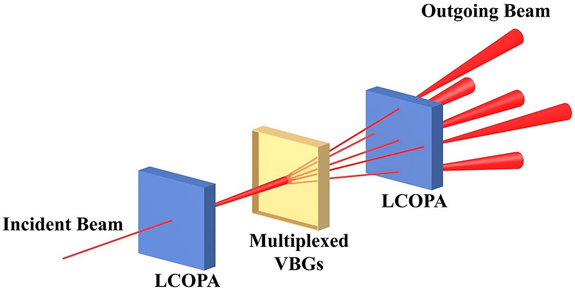
Figure 1.Scheme of the 2D beam scanning system. The incident beam (outgoing from the first stage addressing LCOPA) into multiplexed VBGs is first deflected to each amplified angle, then the second LCOPA finely controls and fills the beam in each exit angle. The LCOPA is capable of achieving precise angular deflection of the beam within the cone-shaped range.
In the design process, the basic parameters of the VBGs include the incident angle as well as the corresponding exit angle of each channel, the rotation angle between each channel and the number of channels. For a single grating channel, as shown in Figure 2(a), the incident beam is diffracted after passing through the VBG and amplified from
When the Bragg condition is satisfied,
The VBG is recorded at the recording wavelength
where
![]()
Figure 2.(a) Typical schematic of volume Bragg grating recording (purple line) as well as diffraction (red line), where the angle is positive when it is turned counterclockwise from the  .
.
As for the rotation angle between each channel and the number of channels, as shown in Figure 2(b), to describe the wave vector of the beam, it is assumed that the z-axis coincides with the front surface normal of the recording medium. The wave vector of the incident beam is expressed as follows:
Assuming that the incident beam is along the z-axis, then its wave vector is as follows:
Now we set the rotation angle between adjacent channels of the grating to be
Here,
where
It needs to be specified that
2.2 Parametric design
The target deflection angle range for this beam scanning system is set as ±35°, the working wavelength is 1064 nm and
As high-level DE is expected, it is essential to balance the refractive index modulation (RIM) of each channel and the thickness of the grating. The DE
![]()
Figure 3.Relationship between grating thickness and diffraction efficiency as well as that between refractive index modulation and diffraction efficiency, under  and
and  . The red line corresponds to Equation (11).
Moreover, crosstalk may occur between channels due to the introduction of peristrophic multiplexing, so it is necessary to optimize the parameters of each channel. The angle selectivity of peristrophic multiplexing[31] is as follows:
When
Eventually, three VBGs for this system as an amplifier are designed, and the key parameters of each VBG are shown in Table 1. Note that the angular selectivity in the grating vector plane is less than 0.12° under the parameters given in Table 1 (a thick grating generally has narrow angle selectivity), which means that the crosstalk between VBGs is faint enough to be ignored because the angular interval between VBGs is much larger than the angular selectivity. As shown in Figure 4, when the incident angle and rotation angle of the incident beam are 1.5° and 0°, respectively, the beam will be deflected to point-M by VBG1. Similarly, the beam will be deflected to point-N by VBG2 when the incident angle and rotation angle of the incident beam are 3° and 30°, respectively. Thus, 2D angular amplification is achieved through three VBGs. With the purpose of realizing a 35° deflection range for the system, the LCOPA applied should provide a deflection range of at least 5°, and it also determines the angular resolution of the system, which is about several mrad[35,36]. It is possible for the overall transmission to reach more than 30% if the VBGs are lossless[18,23].
![]()
Figure 4.Schematic diagram of three VBGs working as an amplifier. The beam is deflected to point-M by VBG1 when the incident angle and rotation angle of the incident beam are 1.5° and 0°, respectively, and is deflected to point-N by VBG2 when the incident angle and rotation angle of the incident beam are 3° and 30°, respectively.
| Rotation angle | Peristrophic | Number | Incident | Exit | Grating | Slant | ||
|---|---|---|---|---|---|---|---|---|
| Grating | between | angular selectivity | of | angle in the | angle in the | period | angle | Thickness |
| number | channels | channels | air | air | ||||
| VBG1 | 60 | 20.94 | 6 | 1.5 | 10 | 5318.1 | 92.84 | 3 |
| VBG2 | 30 | 10.3 | 12 | 3 | 20 | 2685.1 | 95.62 | 3 |
| VBG3 | 20 | 6.67 | 18 | 4.5 | 30 | 1820.2 | 98.28 | 4 |
Table 1. Key parameters of the designed three VBGs.
3 Experimental details
To realize the proposed cascaded peristrophic multiplexed grating system, VBG1, VBG2 and VBG3 are fabricated and tested. After fabrication and testing of the three VBGs, they are integrated into one whole by refractive index matching liquid.
The fabrication process of each VBG based on PTR glass mainly contains two steps: sequential exposure and subsequent heat treatment. In the exposure process, the PTR glass is placed in an asymmetric dual-beam interference light field. In order to obtain the maximum contrast of interference fringes, an attenuator is inserted into one of the beams to ensure that the laser power of both beams is equal inside the medium. A He-Cd laser (Kimmon Electric Model IK3501R-G) with a wavelength of 325 nm and transverse electric (TE) polarization is used as the recording light source. The intensities of the two collimated beams are kept equal as required for obtaining maximum interference fringe contrast. Due to peristrophic multiplexing, the channels in the same gratings share the same light path setup. Take VBG1 for example, after the exposure of the first channel, the PTR glass is rotated by 60° around the normal of the grating surface, and then the second exposure is carried out as before to record a new channel. Therefore, three exposure setups with different interference angles are needed for the exposure of VBG1, VBG2 and VBG3. The exposure dosage of PTR glass samples for each channel is set to 60 mJ/cm2 in VBG1, 30 mJ/cm2 in VBG2 and 25 mJ/cm2 in VBG3. After completing the exposure process, the samples are all heat-treated at 510°C for VBG1 for 1 h, VBG2 for 2.5 h and VBG3 for 2.5 h (the temperature is raised from 20°C with a heating rate of 10 K/min). The samples are finally polished to remove surface crystalline defects caused by heat treatment.
The scheme of DE measurement of multiplexed VBGs is shown in Figure 5. The sample is positioned on a motorized rotational stage with a step of 0.2686 mrad. A semiconductor laser source with a wavelength of 1064 nm, divergence of 0.48 mrad and waist diameter of 1.2 mm is used for testing. A linear polarizer is applied to select TE or transverse magnetic (TM) polarization and a beam expander is set to reduce the divergence to 0.096 mrad. Different grating channels are tested using a self-made sample stage that allows the sample to be rotated around the front surface normal. The intensity of the transmitted zeroth-order beam (I0) is measured using a fixed power meter and that of the minus first-order diffracted beam of the different grating channel (I–1) is measured using an adjustable power meter (both Thorlabs, S120VC). The fixed power meter is placed in the direction of the transmitted zeroth-order beam and the adjustable one is placed in the direction of the diffracted beam. The testing process starts with rotating the sample around the front surface to the corresponding channel, and then angle scanning is implemented. A LabVIEW program is written to collect the angle and intensity data: each time the data is collected, the stage is rotated over a step. The relative DE is calculated as follows:
Due to peristrophic multiplexing, other channels may be read out when scanning one grating channel, but it does no harm to the calculation of DE; a detailed description can be found in the Supplementary Information.
![]()
Figure 5.Scheme of DE measurement of multiplexed VBGs. The sample is positioned on a motorized rotational stage and different grating channels are tested using a sample stage, which allows the sample to be rotated around the front surface normal.
In addition, the VBG recorded in PTR glass has a dual-channel characteristic, allowing us to measure the exit angle precisely and conveniently. The detailed mechanism is described in Ref. [30]. Still, it should be pointed out that the exit angle measured through this characteristic is always opposite to the designed value.
4 Results and discussion
The respective performances of the fabricated multiplexed VBG1, VBG2 and VBG3 are tested individually. Figure 6(a) presents the DE and deviation from the expected Bragg angle of each channel in the three VBGs. Figures 6(b) and 6(c) give the angle selectivity curves (incident angle and exit angle, respectively) of the first channel in each monolithic grating and at the same time demonstrate the validity of Equation (13), since the curves conform to the expected Bragg diffraction characteristics.
![]()
Figure 6.(a) DE and deviation angle of each channel. Experimental angle selectivity curves for the incident angle (b) and exit angle (c) of the first channel in each grating.
There is slight difference between the experimental and expected Bragg angles for all the grating channels, which is attributed majorly to the angle error in the interference exposure process and minorly to the sample positioning error both in the exposure process and the test process[30].
For TE polarized incident light, the maximum DEs for the three VBGs are 99.18%, 88.64% and 65.36%, respectively. Subtle difference in DE between channels in the same grating (with a root-mean-square deviation of less than 3.4%) may result from the inhomogeneities of glass doping and the exposure field. The insufficient DE of VBG2 and VBG3 is thought to be due to the reduced exposure dosage, which leads to a low-level RIM[37,38].
It is worth noting that there is no simple method to measure the exact RIM of the grating sample, so the most effective way is to fit the RIM of each channel through the DE curve of the sample. The fitting procedure of the RIM is consistent with Ref. [39], where a root-mean-square error function is applied to evaluate the coefficient of coincidence of the experimental and theoretical DE curves, which has a precision of approximately 10–5 order of magnitude. Figure 7 shows the RIM fitting curve of the first channel of each monolithic VBG and its picture. Compared with VBG1, the extended heat treatment time of VBG2 makes up the reduced exposure dosage to a certain extent. The insufficient RIM of VBG3 mainly comes from the effect of gradient of refractive index (GRIN)[40] since VBG2 and VBG3 have almost the same fabrication parameters but different thicknesses. The total RIM of a sample would be calculated by summing the RIM of each channel, which is 1.16 × 10⁻³ for VBG1, 1.57 × 10⁻³ for VBG2 and 1.37 × 10⁻³ for VBG3. Since the upper limit of the dynamic range of PTR glass is about 2 × 10⁻³[34,41], it is possible to have DE increased as long as the sample reaches a higher RIM.
![]()
Figure 7.The RIM fitting curve of the first channel of each monolithic VBG and the corresponding picture. The total RIM of a sample would be calculated by summing the RIM of each channel, which is 1.16 × 10⁻³ for VBG1 (a), 1.57 × 10⁻³ for VBG2 (b) and 1.37 × 10⁻³ for VBG3 (c).
The transmittances at 1064 nm of the three VBGs are tested to be 73.52%, 80.03% and 84.37%, respectively, through a spectrophotometer (PerkinElmer Lambda 950), and they could be enhanced by reducing the absorption of photo-reduced silver[42] and the scattering of NaF[43].
Using several pieces of PTR glass to form a complete multi-channel is a simple way to improve the DE. For instance, VBG3 can be replaced by two pieces of 3 mm thick gratings with 9 channels. It is easier for nine-channel gratings to achieve a high DE since it is possible for each channel to allocate more modulation without worrying about the upper limit of the RIM. However, a more elegant way is assigning channels equally to three VBGs. As the number of channels in VBG1 is much fewer than that in VBG3, it is propitious to record part of the channels of VBG3 in VBG1.
Furthermore, in order to achieve a larger angular deflection range for the system, additional gratings with a larger exit angle need to be stacked, which may require more channels. It is foreseeable that dealing with more channels and maintaining a high DE will be the major challenges for the proposed 2D angle amplifier when facing a larger deflection range.
5 Conclusions
A 2D angle amplifier based on PMVBGs with a discrete 2D angle deflection range of ±30° is designed and demonstrated. A calculation method is firstly proposed to optimize the number of channels to a minimum. The application of peristrophic multiplexing reduces the performance difference in one bulk of the grating, while no need to deliberately optimize the fabrication process. The results reveal that the maximum relative DE reaches more than 99%, while the minimum is about 55%, but there is only subtle difference in DE between channels in the same grating. The insufficient DE of VBG2 and VBG3 is thought to be due to the reduced exposure dosage. The deviation of the Bragg incident and exit angles from the expected values is less than 0.07°, and the total RIMs of the three VBGs are fitted to be 1.16 × 10⁻³, 1.57 × 10⁻³ and 1.37 × 10⁻³, respectively. Assigning channels equally to multiple VBGs or dividing VBGs into multiple pieces of PTR glass is considered a proper way to improve the DE of the gratings. Further, the proposed method is flexible to adapt to a larger deflection range, which can be achieved by increasing the number of gratings and channels.
References
[1] R. Morris, C. Jones, M. Nagaraj. Micromachines, 12, 247(2021).
[2] S. Lin, Y. Chen, Z. J. Wong. Nanophotonics, 11, 2617(2022).
[3] A. Akatay, H. Urey. Opt. Express, 15, 4523(2007).
[4] R. Chen, Y. Shao, Y. Zhou, Y. Dang, H. Dong, S. Zhang, Y. Wang, J. Chen, B. F. Ju, Y. Ma. Nano Lett., 22, 1595(2022).
[5] P. F. McManamon, T. A. Dorschner, D. L. Corkum, L. J. Friedman, D. S. Hobbs, M. Holz, S. Liberman, H. Q. Nguyen, D. P. Resler, R. C. Sharp, E. A. Watson. Proc. IEEE, 84, 268(1996).
[6] L. Wu, X. Wang, C. Xiong, Z. Huang, R. Zhuo, J. Rao, Q. Tan. Chin. Opt. Lett., 15, 101601(2017).
[7] S. Du, Y. Huang, C. Fu, H. Guo. J. Appl. Opt., 38, 581(2017).
[8] J. Hu, S. Du, H. Guo. Laser Optoelectron. Prog., 56, 110002(2019).
[9] J. Sun, E. Timurdogan, A. Yaacobi, E. S. Hosseini, M. R. Watts. Nature, 493, 195(2013).
[10] Y. Zhu, S. Zeng, L. Zhu. Photonics Res., 8, 375(2020).
[11] N. Alshamrani, A. Grieco, A. Friedman, K. A. Johnson, M. S. Kim, F. Floris, P. O’brien, Y. Fainman. J. Light. Technol., 39, 4201(2021).
[12] W. B. Lee, C. S. Im, C. Zhou, B. Bhandari, D. Y. Choi, S. S. Lee. Photonics Res., 10, 248(2022).
[13] F. Kimura. Proceedings of the International Display Workshops, 1227(2012).
[14] Z. W. Yu, B. Zhang, S. Y. Liu, Y. J. Wang, J. G. Lu. J. Disp. Technol., 12, 721(2016).
[15] J. Kim, C. Oh, S. Serati, M. J. Escuti. Appl. Opt., 50, 2636(2011).
[16] S. Serati, C. L. Hoy, K. Kluttz, J. Stockley, C. Hale. Opt. Eng., 56, 031211(2016).
[17] M. Sakamoto, H. T. Nhan, K. Noda, T. Sasaki, T. Kamei, T. Sakai, Y. Hattori, N. Kawatsuki, H. Ono. Appl. Opt., 60, 2062(2021).
[18] Z. He, F. Gou, R. Chen, K. Yin, T. Zhan, S. T. Wu. Crystals, 9, 292(2019).
[19] Z. He, K. Yin, S. T. Wu. Light Sci. Appl., 10, 134(2021).
[20] Y. Li, Z. Luo, S. T. Wu. Crystals, 12, 349(2022).
[21] R. W. Eason, A. J. Boyland, S. Mailis, P. G. Smith. Opt. Commun., 197, 201(2001).
[22] W. C. Wang, C. L. Tsui. Sens. Actuators A Phys., 188, 277(2012).
[23] P. F. McManamon, P. J. Bos, M. J. Escuti, J. Heikenfeld, S. Serati, H. Xie, E. A. Watson. Proc. IEEE, 97, 1078(2009).
[24] O. M. Efimov, L. B. Glebov, L. N. Glebova, K. C. Richardson, V. I. Smirnov. Appl. Opt., 38, 619(1999).
[25] Z. Yaqoob, M. A. Arain, N. A. Riza. Appl. Opt., 42, 5251(2003).
[26] A. L. Glebov, A. Sugama, V. I. Smirnov, S. Aoki, V. Rotar, M. G. Lee, L. B. Glebov. IEEE Photon. Technol. Lett., 19, 701(2007).
[27] L. Cao, Y. Zhao, Q. He, G. Jin. Proc. SPIE, 6832, 683216(2007).
[28] F. Gao, X. Yuan, X. Zhang. Chin. Opt. Lett., 14, 060502(2016).
[29] I. W. Smith, M. K. O. Holz. and , U.S. Patent 7,215,472 ().(2007).
[30] P. Chen, Y. Jin, D. He, J. Chen, J. Xu, J. Zhao, Y. Zhang, F. Kong, H. He, J. Shao. Opt. Express, 26, 25336(2018).
[31] K. Curtis, A. Pu, D. Psaltis. Opt. Lett., 19, 993(1994).
[32] H. Kogelnik. Landmark Papers on Photorefractive Nonlinear Optics(1995).
[33] L. Wu, X. Wang, C. Xiong, Z. Huang, Q. Tan, M. Li. Opt. Eng., 55, 116115(2016).
[34] S. Kaim, S. Mokhov, I. Divliansky, V. Smirnov, J. Lumeau, B. Y. Zeldovich, L. B. Glebov. J. Opt. Soc. Am. A, 32, 22(2015).
[35] L. L. Tian, F. Chu, W. Duan, R. Li, X. Q. Gu, L. Li, Q. H. Wang. Opt. Commun., 481, 126525(2021).
[36] C. Wang, Q. Wang, Q. Mu, Z. Peng. Opt. Commun., 506, 127610(2022).
[37] J. Lumeau, L. Glebova, V. Golubkov, E. D. Zanotto, L. B. Glebov. Opt. Mater., 32, 139(2009).
[38] J. Lumeau, L. B. Glebov. Opt. Mater. Express, 3, 95(2013).
[39] P. Chen, D. He, Y. Jin, J. Chen, J. Zhao, J. Xu, Y. Zhang, F. Kong, H. He. Opt. Express, 26, 157(2018).
[40] J. Lumeau, L. B. Glebov. Appl. Opt., 54, 1587(2015).
[41] O. M. Efimov, L. B. Glebov, H. P. Andre. Appl. Opt., 41, 1864(2002).
[42] L. B. Glebov, V. I. Smirnov. Proc. SPIE, 5273, 396(2004).
[43] J. Lumeau, L. Glebova, L. B. Glebov. Opt. Mater., 36, 621(2014).

Set citation alerts for the article
Please enter your email address
© Copyright 2018-2021 | Chinese Laser Press. All Rights Reserved 沪ICP备15018463号-20