Abstract
A photonic-assisted radio frequency (RF) down-converter integrating with the optoelectronic oscillator (OEO)-based high quality local oscillator (LO) has been proposed and experimentally demonstrated. The LO and the RF input signal are mixed at the same phase modulator and photo-detector (PD) of the OEO-loop without any additional modulator or PD. The working bandwidth of the proposed RF down-converter is nearly from 2.5 to 10 GHz. The performance of the proposed down-converter is presented and the spurious frequency dynamic range at frequency of 5.5 GHz with the LO at 6.138 GHz is measured to be 98.4 dB–Hz2∕3. The influences that the frequency range and power of the RF input signal bring to the system are discussed as well.1. INTRODUCTION
Photonic-assisted radio frequency (RF) down-converters have received extensive interest, owing to the advantages of their large processing bandwidths, fast reconfigurability, tunability, low loss and immunity to electromagnetic interference [1,2], which are attractive for application in radio-over-fiber systems and arrayed signal processing [3–6]. For conventional photonic-assisted microwave down-conversion systems, the RF signal will first be up-converted to the optical domain by the modulator and mixed with the RF local oscillator (LO) at a modulator and down-converted to baseband or intermediate frequency (IF) with a low-speed photo-detector (PD) [6–14]. Among them, the LOs based on optoelectronic oscillators (OEOs) have attracted a lot of research interest because they possess large bandwidth, fast tunability, and high purity [6,10,11]. To avoid the impact on the oscillation of the OEO, the RF signal should be isolated from LO, such as by realizing an OEO-based LO with an oscillation frequency at nearly half the signal for down-converting so that the signal could not leak to the modulator directly, as proposed in [6], employing the wavelength filter to filter out the RF input signal to realize the isolation as presented in [13], or introducing another modulator and PD for the photonic-assisted down-conversion section [14]. In this paper, a simple RF photonic down-converter based on OEO is proposed and experimentally demonstrated. The isolation between the RF input signal and the OEO-based LO is realized by setting the oscillation frequency of the OEO detuned with the frequency of RF signal, which can be guaranteed by tuning the center frequency of the microwave photonic filter (MPF) in the OEO loop to change the oscillation frequency of the OEO. Moreover, the mixing process is at the PM and PD of the OEO-loop without any additional modulator or PD. The working bandwidth of the proposed photonic-assisted RF down-converter can cover from 2.5 GHz to multi-tens GHz, which is limited by the minimum bandwidth of the optical tunable filter and the maximum bandwidth of the PM and PD. The performance of the RF down-converter is analyzed and the spurious free dynamic range (SFDR) at an RF frequency of 5.5 GHz with the LO at 6.138 GHz is measured to be as high as . The limitations in the frequency range and power of the RF input signal have also been discussed.
This paper is organized as follows. The principle of the proposed RF photonic down-converter is described in Section 2. This section also discusses the operating frequency range of the down-converter. Experimental results demonstrating the down-converter’s performance and its application condition are described in Section 3. Finally, a summary is presented in Section 4.
2. PRINCIPLE
The schematic diagram of the proposed RF photonic down-converter integrating with the OEO-based LO is shown in Fig. 1. In the dashed frame of Fig. 1, the circular loop with a PM, tunable bandpass filter (TBPF), PD, and power amplifier (PA) forms an OEO for the high quality LO, the frequency of which can be tuned by changing the bandwidth of TBPF [11]. The modulator and the PD of the OEO loop are reused for up-converting and down-converting of the RF input signal. A continuous wave (CW) laser centered at is used as the optical carrier for phase modulation and modulated by the combination of the RF signal and the LO with the frequency of and , respectively. The modulated signal is filtered by the TBPF and sent into the PD for down-converting. After the PD, the signal is split to two parts by the coupler; one goes back to the LO loop to keep the oscillation and the other will be filtered by the direct current (DC) block and the low pass filter (LPF) to achieve the down-converted signal, which is the beat signal () between the RF signal and the LO. To avoid the influence of the RF input signal and the new generated signal on the oscillation of the OEO, the LO should be isolated from them as described below.
Sign up for Photonics Research TOC. Get the latest issue of Photonics Research delivered right to you!Sign up now
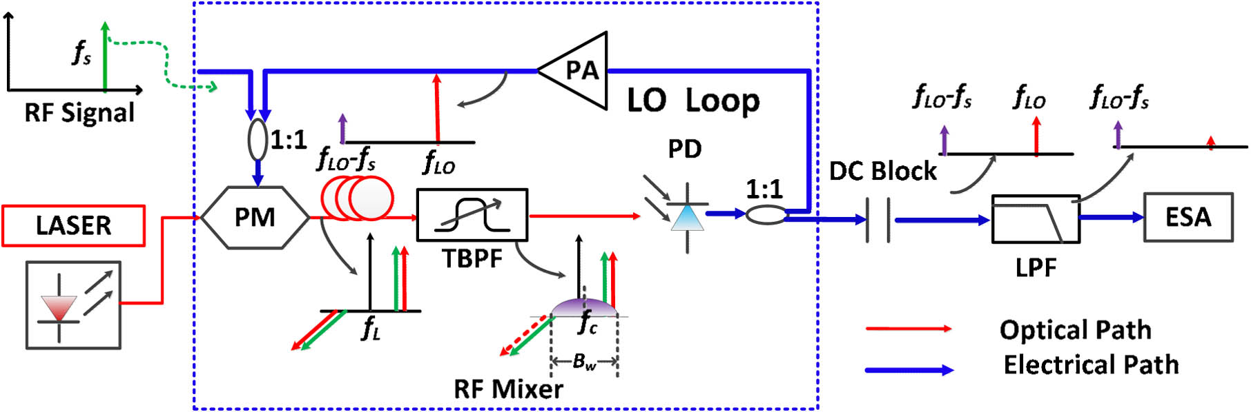
Figure 1.Schematic diagram of the simple RF photonic down-converter integrating with OEO-based LO.
Under the structure mentioned above, the PM, TBPF, and PD construct a tunable band pass MPF [15] in the OEO loop [11]. The possible oscillation frequency range of the OEO is determined by the passband of the MPF. The bandwidth of the MPF is , which is determined by the interval () and equals . The center frequency of the MPF is nearly half of the bandwidth (Bw) of TBPF [15]. The isolation between the RF input signal and the LO can be simply realized by keeping the RF signal out of the passband of MPF and the LO in the passband of the MPF, while all the first order of the modulated RF signal is in the passband of optical filter and only either the or order of the LO modulated signal would exist after the filter, as shown in Fig. 1, with a relationship of . So, after the PD (i.e., after the MPF), the RF signal is vanished and the LO is maintained; meanwhile the beat frequency signal between them is also generated to be the down-converted signal desired. The interval between the carrier and the center of the TBPF () partially determines the ability of down-converter, since the frequency of the down-converted signal would be larger than . In theory, the narrower the separation () the better, as long as the separation is larger than zero, and an oscillator mode would exist to serve as the LO. So the frequency of the RF signal should be in the range of , and the frequency of the converted signal is at a range of . The frequency-conversion process acts as the down-conversion process on the condition that the frequency of the converted signal () is lower than the frequency of the RF input signal (), i.e., . Even though the frequency of the RF input signal would be changing, the relationship can be guaranteed by simply tuning the bandwidth of the TBPF to alter the frequency of LO [11]. After the PD, there are mainly two frequency components that would exist: the small beat signal and the LO. Both of them will go back to the LO loop and be amplified by a PA. The small beat signal at a frequency of () is the down-converted signal desirable, but it is not welcome to the OEO loop. But fortunately, as the beat signal is out of the passband of the MPF, it will vanish due to the same reason as the vanishing of the RF signal inside the OEO loop. Although only the first-order phase-modulated sidebands have been taken into account in theory, there are still more much lower sidebands that exist, such as first-order sidebands generated by using RF to phase modulate the first-order sidebands generated by the LO, and likewise. Most of the sidebands would be vanished due to the same reason as the vanishing of the RF signal and down-converted signal inside the OEO loop.
This is what we use in this RF photonic down-converter to eliminate the impact of the RF signal and the down-converted signal on the oscillation of the OEO. The mixing between the signal and the LO is at the same PM and PD of the OEO loop without any additional modulator or PD. The working bandwidth of the down-converter is nearly from to , which could be adapted by changing the frequency of the LO.
3. EXPERIMENT SETUP AND DISCUSSION
In the experiment, the parameters of the system in Fig. 1 are listed as follows: the optical power from the CW laser is 13 dBm, with 1 kHz line-width and center wavelength of 1550.024 nm, the bandwidth and half-wave voltage of the PM are 40 GHz and 7 V, respectively, the TBPF is realized by the wave-shaper (Finisar 1000s) with a tunable bandwidth from 10 GHz to more than several hundred GHz, the bandwidth of the PD is 10 GHz, and the gain of the PA is about 30 dB to make the gain of the loop larger than 1 to obtain and keep the oscillation. The electrical spectrum of the down-converted signal is measured by the electrical spectrum analyzer (ESA). As the minimum bandwidth of the TBPF and the maximum bandwidth of the PD are all 10 GHz, the frequency of the LO should be in the range of 5–10 GHz [11], so the working bandwidth of the down-converter in our experiment is nearly from to 10 GHz, as discussed above.
In order to investigate the performance of the RF photonic down-converter based on OEO, a two-tone test RF signal centered at a frequency of 5.5 GHz with a separation of about 10 MHz, generated by the Agilent 8267D, is injected into the PM. The bandwidth of the TBPF in this experiment is 13 GHz and the center frequency is set properly near the carrier. The LO generated by the OEO is at a frequency of 6.138 GHz, as shown in Fig. 2(a), which is applied to down-convert the signal to IF or baseband. The frequency of the LO is lower than half of the bandwidth of the filter (), which is mainly because the shape of the filter is not a rectangle and the gain spectrum of the PA is not so flat. A single mode fiber with a length of about 200 m is introduced to the OEO loop to obtain the delay and lower the phase noise of the LO, which also determines the mode interval of the OEO.

Figure 2.(a) Electric spectrum of the OEO-based LO at a frequency of 6.138 GHz and (b) the picture of the phase noise.
The phase noise picture of the LO at 6.138 GHz is shown in Fig. 2(b), and the phase noise at an offset of 10 kHz relative to the center frequency of the oscillation of the OEO is below . The experimental results of the RF photonic down-converter are also measured and shown in Fig. 3. The down-converted signal measured by the ESA is shown in Fig. 3(a) and the down-conversion gain is about (input: 8 dBm at 5.5 GHz, output: at 627.7 MHz), which is better than the down-converter proposed in [9,14], thanks to only one PM and PD being applied in our system to achieve a higher conversion gain. The SFDR of the link is also measured as described in Fig. 3(b). As the linewidth of the CW laser used in the link is only 1 kHz and no EDFA is used in this link, the noise floor of the link can be lower than based on the estimation method presented in [16]. In these experiment results, the SFDR is measured to be as high as , which is nearly at the same level relative to other technologies [9,17,18].
Figure 3.Experimental results of the LO-integrated down-conversion APL at frequency of about 6.138 GHz: (a) electrical spectrum of down-converted IF signal and (b) the measured SFDR.
We would like to point out the application condition of the proposed RF photonic down-converter in reality. As the filter is a nonideal rectangle and the gain of the PA is not so flat, after the filter, the amplitude of the and order RF modulated signals are not equal and the or order of the LO modulated signal is not removed clearly. The RF signal will exist and the LO will be eliminated a little after the filter and PD, which will reduce the isolation rate. So, there would be a limitation in the power of the RF input signal and the frequency difference () between the signal and the LO. If the frequency difference is settled, there will be a limitation in the input power of the RF signal. As the frequency of the laser can be tuned with a step of about 125 MHz and the tuning step of the optical TBPF is nearly 1 GHz, the interval between the center frequency of the filter and the laser could be tuned by a minimum step of about 125 MHz and the minimum separation between them can be lower than . If , the two-tone signal may exist after the PD and be amplified by the amplifier to impact the LO, so we just set the . The maximum power of the RF input signal to keep the oscillation of the OEO at different is experimentally measured and presented in Fig. 4. If , when the power of the input two-tone signal is larger than 0 dBm, the oscillation of the LO will vanish. If the is larger, the minimum input power that will result in the vanishing of the LO will be higher, as shown in Fig. 4. So there will be a trade-off between the and the input power of the RF signal. To achieve the optimized performance of the down-converter, a widely TBPF with an approximate rectangle shape would be required.
Figure 4.Operation condition of the LO vanishing point induced by the high input RF power at different .
4. CONCLUSION
In this paper, we propose and experimentally demonstrate an RF photonic down-converter integrated with an OEO-based LO. The frequency of the RF input signal is detuned with the oscillation frequency of the OEO so that the mixing between the RF signal and the LO can be at the same PM and PD of the OEO loop without any additional modulator or PD. This is the simplest design for down-conversion system based on high quality OEO, as far as we know. The proposed RF photonic down-converter can be applied in a large frequency range nearly from to , which is determined by the oscillation frequency of the OEO and only limited by minimum bandwidth of the TBPF and the maximum bandwidth of the phase modulator and the PD. The performance of the down-converter has been measured and the SFDR at a frequency of 5.5 GHz with the LO at 6.138 GHz is measured to be . The limitations in the frequency interval between the RF signal and the LO and the power of the RF input signal in this proposed simple RF down-converter have also been discussed.
References
[1] J. Capmany, D. Novak. Microwave photonics combines two worlds. Nat. Photonics, 1, 319-330(2007).
[2] J. Yao. Microwave photonics. J. Lightwave Technol., 27, 314-335(2009).
[3] T. Kuri, H. Toda, K.-I. Kitayama. Dense wavelength-division multiplexing millimeter-wave-band radio-on-fiber signal transmission with photonic downconversion. J. Lightwave Technol., 21, 1510-1517(2003).
[4] C. K. Sun, R. J. Orazi, S. A. Pappert. Efficient microwave frequency conversion using photonic link signal mixing. IEEE Photon. Technol. Lett., 8, 154-156(1996).
[5] R. Helkey, J. C. Twichell, C. Cox. A down-conversion optical link with RF gain. J. Lightwave Technol., 15, 956-961(1997).
[6] D. Zhu, S. Pan, S. Cai, D. Ben. High-performance photonic microwave downconverter based on a frequency-doubling optoelectronic oscillator. J. Lightwave Technol., 30, 3036-3042(2012).
[7] M. Hossein-Zadeh, K. J. Vahala. Photonic RF down-converter based on optomechanical oscillation. IEEE Photon. Technol. Lett., 20, 234-236(2008).
[8] K.-Y. Tu, M. S. Rasras, D. M. Gill, S. S. Patel, Y.-K. Chen, A. E. White, A. Pomerene, D. Carothers, J. Beattie, M. Beals, J. Michel, L. C. Kimerling. Silicon RF-photonic filter and down-converter. J. Lightwave Technol., 28, 3019-3028(2010).
[9] V. R. Pagán, B. M. Haas, T. E. Murphy. Linearized electrooptic microwave downconversion using phase modulation and optical filtering. Opt. Express, 19, 883-895(2011).
[10] L. Maleki. Sources: the optoelectronic oscillator. Nat. Photonics, 5, 728-730(2011).
[11] X. Xie, C. Zhang, T. Sun, P. Guo, X. Zhu, L. Zhu, W. Hu, Z. Chen. Wideband tunable optoelectronic oscillator based on a phase modulator and a tunable optical filter. Opt. Lett., 38, 655-657(2013).
[12] X. S. Yao, L. Maleki. Optoelectronic oscillator for photonic systems. IEEE J. Quantum Electron., 32, 1141-1149(1996).
[13] W. Shieh, S. X. Yao, G. Lutes, L. Maleki. Microwave signal mixing by using a fiber-based optoelectronic oscillator for wavelength division multiplexed systems. Proceedings of Optical Fiber Communication Conference, 358-359(1997).
[14] T. Sun, C. Zhang, X. Xie, P. Guo, X. Zhu, H. Peng, L. Zhu, W. Hu, Z. Chen. microwave photonic down-conversion based on a wideband tunable optoelectronic oscillator. Asia Communications and Photonics Conference, AF2F.3(2013).
[15] T. Chen, X. Yi, L. Li, R. Minasian. Single passband microwave photonic filter with wideband tunability and adjustable bandwidth. Opt. Lett., 37, 4699(2012).
[16] D. Marpaung, C. Roeloffzen, A. Leinse, M. Hoekman. A photonic chip based frequency discriminator for a high performance microwave photonic link. Opt. Express, 18, 27359-27370(2010).
[17] Y. Gao, A. Wen, H. Zhang, S. Xiang, H. Zhang, L. Zhao, L. Shang. An efficient photonic mixer with frequency doubling based on a dual-parallel MZM. Opt. Commun., 321, 11-15(2014).
[18] T. Jiang, S. Yu, C. Luo, J. Li, R. Zhang, Q. Xie, W. Gu. Digital linearization and full spectrum utilization for phase-modulation photonic downconversion. IEEE Photon. Technol. Lett., 25, 2010-2013(2013).

