
Guangzong Xiao, Bin Zhang, Zhiguo Wang, Yangying Fu, Mengfan Gong. Frequency difference lock-in phenomenon’s weakening by transverse magnetic field in Y-shaped cavity dual-frequency laser[J]. Chinese Optics Letters, 2015, 13(11): 111405
- Chinese Optics Letters
- Vol. 13, Issue 11, 111405 (2015)
Abstract
Orthogonally polarized dual-frequency lasers are widely applied in two-frequency interferometers, ellipsometers, displacement measurement, wave plate measurement, and other measuring systems[
Doyle and White pointed out that the mode competition could be overcome by the presence of a small magnetic field that is normal to the laser axis[
Zhang
Sign up for Chinese Optics Letters TOC. Get the latest issue of Chinese Optics Letters delivered right to you!Sign up now
In 2011, our group developed a novel dual-frequency laser based on the Y-shaped cavity; this laser was called a Y-shaped cavity dual-frequency laser, and we studied its characteristics[
Compared with other dual-frequency lasers with large frequency differences based on the birefringence effect, better frequency difference stability is expected in the developed laser because no birefringent element is in its cavity. Meanwhile, the frequency difference can be tuned to a certain value for adjusting to different applications for the abovementioned superiorities. The Y-shaped cavity dual-frequency laser is expected to bring about a revolution in precision measurement. However, the frequency difference lock-in phenomenon still exists, thereby affecting its performance in the measurement field.
In this Letter, we report the experimental progress in weakening the frequency difference lock-in phenomenon in a Y-shaped cavity dual-frequency laser. We developed a tunable and convenient transverse magnetic field setup and tested its magnetic field intensity distribution. Then, the basic principle of weakening the frequency difference lock-in phenomenon by a transverse magnetic field was analyzed. Moreover, we report the preliminary experimental results and discuss the minimal frequency difference variations with the transverse magnetic field intensity. Conclusions are given last.
Figure
![]()
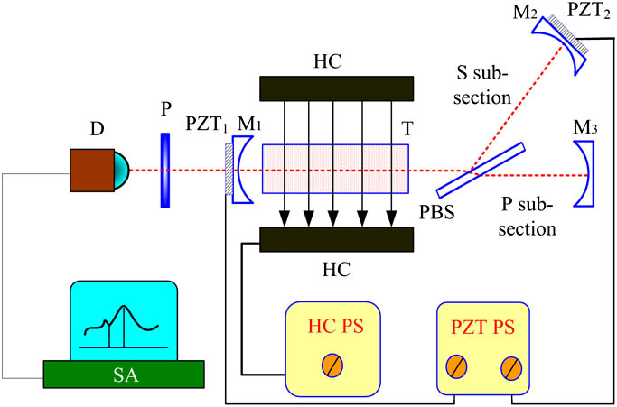
Figure 1.Experiment setup of weakening frequency difference lock-in phenomenon in a Y-shaped cavity dual-frequency laser. PZT1, PZT2: piezoelectric transducer; P: polarization plate; D: photoelectric detector; SA: spectrum analyzer; HC: Helmholtz coil pair; HCPS: power supply for Helmholtz coil pair; PZTPS: power supply for PZT.
First, the two terms used in this Letter are defined as follows. P-light indicates that the electric field vector is perpendicular to the plane of incidence, whereas S-light indicates that the electric field vector is parallel to the plane of incidence. The Y-shaped cavity dual-frequency laser in Fig.
As shown in Fig.
Early studies have indicated that the smallest magnetic field intensity needed to completely eliminate the frequency difference lock-in phenomenon and keep the frequency difference stable for orthogonally polarized dual-frequency He-Ne lasers is about 18 mT. Meanwhile, the region of the homogeneous magnetic field is sufficiently wide to cover the laser tube. A magnet is usually applied to produce a transverse magnetic field because of its simplicity and convenience. However, tuning its magnetic field intensity is difficult. The Helmholtz coil pair is a common method used to obtain a tunable homogeneous magnetic field. The conventional Helmholtz coil pair provides a uniform field at the center of the system. However, the ratio of the high-uniformity region and its volume is so small that a large Helmholtz coil pair is needed for the Y-shaped cavity dual-frequency laser, and such a size makes the device inconvenient to use.
Fortunately, the cube coil pair is a better choice because of its magnetic field strength uniformity and uniform field range. A self-built system comprising two identical square coils is used to provide a uniform magnetic field over a considerable part of the volume, as shown in Fig.
![]()
Figure 2.Configuration of the cube coil pair.
Two coils made of enamel wires that are wound on the square frameworks are connected in a series. The diameter of the enamel wire is about
Given that the length of the gain tube is about 93 mm, the length of the cube is set to
For convenience, a Cartesian coordinate system
![]()
Figure 3.Magnetic field intensity distribution along the
The uniform field range is about 98 mm, with the magnetic field intensity of 4.2 mT, when the current
According to the laser principle, the longitudinal mode spacing
![]()
Figure 4.Distribution of longitudinal modes along the frequency axis. Dashed lines represent P-light; solid lines represent S-light; arrows indicate the directions along which the longitudinal modes move while the voltage applied to PZT2 is increasing.
The minimal frequency difference between two polarized lights can be observed using the frequency spectrum analyzer. Without a magnetic field the minimal frequency difference is about 12 MHz, which is called the lock-in frequency difference that stems from the strong competition between two polarized lights. After adjusting the current in the enamel wire of the loops, the magnetic field intensity near the discharge tube at different parameters changes. The minimal frequency difference varies with different magnetic field intensities, as shown in Fig.
![]()
Figure 5.Minimal frequency difference varying with different magnetic field intensity.
When the magnetic field intensity increases the minimal frequency difference becomes smaller, demonstrating that the ability of weakening the frequency difference lock-in phenomenon is strengthened with a larger magnetic field intensity. Furthermore, the frequency difference lock-in phenomenon is eliminated when the magnetic field intensity reaches 9 mT. It is important to note here that both the lock-in frequency difference and the smallest magnetic field intensity to eliminate the frequency difference lock-in phenomenon are smaller than those of ordinary dual-frequency lasers. That is because the isotropic properties of intracavity components in a Y-shaped cavity dual-frequency laser are better than others.
However, the minimal frequency difference when the magnetic field intensity is smaller than 8 mT is larger than that without any magnetic field intensity. This result may be due to the transverse magnetic field splitting the gain profile of the laser into three parts,
When the current through the enamel wire is set as
![]()
Figure 6.Frequency differences tuning with the voltage applied on PZT2 when the magnetic field intensity is about 9 mT.
In our experiments, the frequency difference lock-in phenomenon is evidently weakened by a transverse magnetic field in the Y-shaped cavity dual-frequency laser. A cube coil pair is chosen to provide a uniform magnetic field because of its tunability and uniformity of magnetic field strength. The relationship between the minimal frequency difference and magnetic field intensity is investigated and analyzed by tuning the cube coil pair current. When the transverse magnetic field intensity is 9 mT, the lock-in effect is not found. Moreover, the minimal frequency difference reaches 0.12 MHz.
The frequency difference can be continuously tuned in the range of 0.12 MHz to 1.15 GHz. The Y-shaped cavity dual-frequency laser is expected to be an optimum light source for heterodyne interferometric sensing and precious laser measurement. Thus, the performances of micro-force measurement and acceleration measurement based on the Y-shaped cavity dual-frequency laser is enhanced. Furthermore, this laser also exhibits a capability of precise measurement of the refractive index and the density of a transparent medium by placing the sample in one subcavity (S subcavity or P subcavity) because of its special structure. Further investigations are being undertaken.
References
[1] Z. Zhao, S. Zhang, P. Zhang, Z. Zeng, Y. Tan, Y. Li. Chin. Opt. Lett., 10, 0328011(2012).
[2] A. Takita, H. Ebara, Y. Fujii. Rev. Sci. Instrum., 82, 123111(2011).
[3] Z. Zhao, S. Zhang, Y. Tan, Y. Li. Chin. Opt. Lett., 10, 0214021(2012).
[4] J. Ding, Q. Feng, L. Zhang, S. Zhang. Appl. Opt., 47, 5631(2008).
[5] H. Wolfgang, N.-R. Stephan, K. Michael. Measurement, 28, 277(2000).
[6] S. Zhang, T. Xu. Prog. Nat. Sci., 15, 586(2005).
[7] S. Zhang, G. Liu. Prog. Nat. Sci., 15, 865(2005).
[8] W. M. Doyle, M. B. White. J. Opt. Soc. Am., 55, 1221(1965).
[9] V. G. Gudelev, V. M. Yasinskiĭ. Sov. J. Quantum Electron., 12, 904(1982).
[10] Y.-Y. Jin, S. Zhang, Y. Li, J. Guo, J. Li. Chin. Phys. Lett., 18, 533(2001).
[11] X. Yan, S. Zhang, Y. Li, Z. Jun. Chin. Phys. Lett., 20, 230(2003).
[12] Y. Zhang, Y. Li, S. Zhang. J. Tsinghua Univ. (Sci. Technol.), 47, 1969(2007).
[13] G. Xiao, X. Long, B. Zhang. Chin. J. Lasers, 38, 03020161(2011).
[14] G. Xiao, X. Long, B. Zhang. Opt. Precis. Eng., 19, 2581(2011).
[15] G. Xiao, X. Long, B. Zhang. Opt. Laser Technol., 43, 1314(2011).
[16] G. Xiao, X. Long, B. Zhang, G. Li. Chin. Opt. Lett., 9, 101201(2011).
[17] G. Xiao, X. Long, B. Zhang, S. Jin. Opt. Laser Technol., 44, 344(2012).
[18] X. Long, G. Xiao, B. Zhang. A displacement sensor based on Y-shaped cavity dual-frequency laser. Chinese Patent(2013).
[19] R. Merritt, C. Purcell, G. Stroink. Rev. Sci. Instrum., 54, 879(1983).

Set citation alerts for the article
Please enter your email address
© Copyright 2018-2021 | Chinese Laser Press. All Rights Reserved 沪ICP备15018463号-20