
Miao Xu, Haodong Shi, Chao Wang, Zhuang Liu, Qiang Fu, Yingchao Li, Keyan Dong, Huilin Jiang. Technology for Integrating Space Object Multidimensional Detection and Laser Communication[J]. Chinese Journal of Lasers, 2021, 48(12): 1206002
- Chinese Journal of Lasers
- Vol. 48, Issue 12, 1206002 (2021)
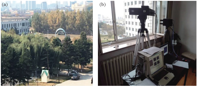
Fig. 1. Full polarization imaging detection. (a) Test scenario; (b) principle prototype
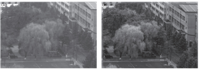
Fig. 2. Polarization imaging test result. (a) Visible light intensity image; (b) polarization image
Fig. 3. Multidimensional oil classification test site and results. (a) Test site; (b) oil location; (c) visible light image; (d) polarization image
Fig. 4. Degree of polarizations of five kinds of oils at different observation angles
Fig. 5. Construction of the CMPI based on DCSP
Fig. 6. Schematic diagram of polarization spectrum imaging
Fig. 7. Design of pupil filter[25]. (a) Distribution of phase plate annular zone; (b) comparison of PSF before and after adding phase modulator
Fig. 8. Imaging effects of each field of view before and after adding modulation element[25]. (a) Free-modulation; (b) 0°; (c) 0.16°; (d) 0.28°
Fig. 9. Reflector components[30]
Fig. 10. Geometric configuration of high-orbit space debris and the laser ranging constellation as well as the position relationship in the XYZ coordinate system[31]
Fig. 11. Flowchart of moving to moving laser pointing prediction method
Fig. 12. Space-based optical system for laser ranging of space targets
Fig. 13. Schematic of rotating paraboloid-based surface
Fig. 14. Overall scheme of one-point to multi-point simultaneous space laser communication system[38]
Fig. 15. Field test diagram of one-point to two-point simultaneous space laser communication
Fig. 16. General function diagram[40]
Fig. 17. Composition of space-based debris monitoring system
Fig. 18. System work flowchart
Fig. 19. Principle prototype of integration of detection and imaging
|
Table 1. Comparison of advantages of several detection technologies


Set citation alerts for the article
Please enter your email address

© Copyright 2018-2021 | Chinese Laser Press. All Rights Reserved 沪ICP备15018463号-20