
Guang-yu LIANG, Liang-lun CHENG, Guo-heng HUANG, Li-min XU. Object Detection of Millimeter-wave Image Based on Spatial-transformer RCNN with Deblurring[J]. Acta Photonica Sinica, 2020, 49(2): 0210004
- Acta Photonica Sinica
- Vol. 49, Issue 2, 0210004 (2020)
Abstract
Keywords
0 Introduction
With increasing need for security inspection of transportation and public places, millimeter-wave imaging systems are developed to automatically determine and locate the corresponding categories of forbidden objects, like knives and guns, on human bodies.
As for enhancing and denoising millimeter-wave images, image processing methods such as wavelet transform, interpolation, and histogram equalization are used. In /1/2, four interpolation methods are investigated to improve the image quality of a Passive Millimeter-Wave (MMW) image. MATEOS J et al.[
At present, the object detection of hidden objects in millimeter-wave image can be roughly divided into two categories: traditional methods and deep learning methods.The traditional methods are mostly used which are generally based on the idea of image classification. XIAO Z L et al.[
Algorithms of object detection based on deep learning are mainly divided into two categories. One is a framework that combines object proposal, and the other is a framework for integrated convolutional networks. Faster R-CNN[
However, the effect based on the traditional method mainly depends on the extracted features, but the low resolution and blurry characteristics of the millimeter-wave image have effect on feature extraction. Although feature extraction of convolutional neural networks is powerful, its robustness to distortion (rotation, scaling, etc.) is very low for small data sets in real-world detection. In the security check of the human body, objects carried by people will be presented in different sizes and angles. So far, there is no deep-learning-based method to study the distortion invariance in object detection of the millimeter-wave image. In order to solve the problem of detecting objects of different sizes, shapes, and angles in a millimeter-wave image, a conventional method is generally employed. For example, low order Hu moments and other four shape features are combined together[
Because of the these problems, we propose a detection framework of Spatial-Transformer Regional Convolutional Neural Network (ST-RCNN) with deblurring, combining non-blind deblurring and Spatial Transformer Networks (STN)[
1 Active millimeter-wave cylindrical scanning imaging
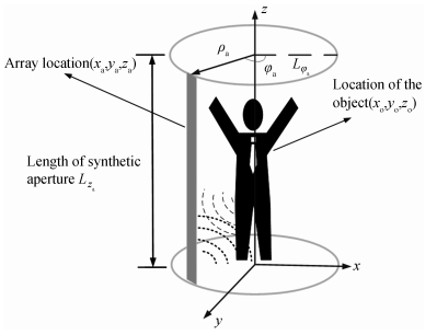
The antenna array rotates around the axis of the human body at the circumference of the radius ρa, and form a synthetic aperture in the direction of the circumference φa, φa∈[0, 2π). Its position is ra= xa, ya, zaT. The coordinate of the imaging point is defined as ro= xo, yo, zoT, where | ro| ≤D, D is the imaging area of the object. The length of the antenna array is Lza. The cylindrical aperture data during imaging is formed by sampling in directions of φa and za. The imaging frame is shown in
![]()
Figure 1.Model of millimeter-wave cylindrical scanning imaging
The Green′s function of the spatial domain is defined as
where the wave number of the free space is represented by k0, k02 =kx2+ky2+kz2.
where d
The scattering field us is obtained by linearly accumulating the weight of the objective function o (
kx, ky, kz replaced by the polar cylindrical coordinates kr,
The algorithm of Stolt-mapping can be used for interpolation operations. Finally, the objective function is
2 Structure of proposed network
Based on the principle of active millimeter-wave cylindrical scanning imaging, a millimeter-wave wideband T/R transceiver (frequency range from 24 GHz to 30 GHz), single-shot single-receiver wideband switch array, three-dimensional real-time imaging and detection framework of our ST-RCNN with deblurring are used to achieve fast 3D imaging of high resolution and object detection of dangerous goods. The object detection frame is more robust to translation, scaling, and rotation.
![]()
Figure 2.Frame for object detection of millimeter-wave images
2.1 Network of non-blind deblurring
At present, the quality of millimeter-wave imaging is generally low, with more noise and poor contrast. The deblurring of the millimeter-wave image should meet the requirements: the details of the image are enriched as much as possible, and the clarity should be enhanced; losing important features contained in the image should be avoided; no additional noise should be introduced during this process. To improve the quality of the millimeter-wave image, the image can be used for subsequent feature extraction and image recognition.
The overall non-blind deblurring architecture is shown in
![]()
Figure 3.Network of non-blind deblurring
2.1.1 Estimation of blur kernel
The blurred image can be regarded as a convolution operation by the latent image and the blurring kernel, and the blur process is referred to
whereB is a blurred image, I is a latent image, K is a blur kernel, N is additional noise, and
The blur kernel is estimated as follows:
Step 1:Roughly initializing the value of K for the input blurred image.
Step 2: Solving Eq. (8) by minimizing I, u and g while determining other variables, and Eq.(9) by Fast Fourier Transform (FFT).
where α and β are penalty parameters, u and g are auxiliary variables, λ, γ and ω are weight parameters, and D (I) is a norm. Given I, the solution of u is
Eq. (10) is similar for the solution of g. The first term in Eq. (8) limits the convolution result of the latent image and the blur kernel to be similar to the input blur image. The second term retains a large gradient on the image gradient.
Step 3: Iterating Step 2 for i times, and finally the blur kernel K and the intermediate value of the latent image I are output.
2.1.2 Network of convolutional denoiser
A convolutional neural network combined with a model-based optimization is to achieve deblurring of millimeter-wave images. The noise image is synthesized by first applying a blur kernel and then adding additive Gaussian noise with a noise level σ. Then it is input to the CNN to get the priori information. It is integrated into a model-based optimization method to achieve deblurring of millimeter-wave images. The convolutional Denoiser is shown in
![]()
Figure 4.Structure of convolutional denoiser network
Among them, to capture content information, the receptive field is expanded by continuous dilated convolution. The CNN consists of 7 layers of dilated convolution and the dilation factors are set to 1, 2, 3, 4, 3, 2, 1, in turn. The dimension of the feature map is 64. The activation functions used are all ReLU functions. Batch normalization is used from the second layer.
The obtained image prior information is integrated into the model-based optimization algorithm to achieve image deblurring.
2.2 Detection framework of ST-RCNN
The STN is inserted into the feature extraction network VGG16[
![]()
Figure 5.Structure of ST-RCNN
The basic network for feature extraction of Faster R-CNN is VGG16 with 13 convolutional layers. The first two layers separately contain 64 convolution filters followed by a max-pooling layer. Next are two convolutional layers containing 128 convolution filters and a max-pooling layer. Three convolutional layers and a pooling layer are performed. The last six convolutional layers contain 512 convolutional filters respectively and are connected to the max-pooling layer after the tenth and thirteenth convolutional layers. The obtained feature map is input into the Region Proposal Networks(RPN)to obtain Region of Interest (RoI). And then combined with the feature map, the result is output after the RoI pooling layer and the Fully-Connected (FC) layers. The STN network is combined to the first layer of the convolutional layer of VGG16. The RELU function is used as a nonlinear activation function.
2.2.1 Spatial-transformer network
The spatial transformer network is mainly composed of three parts: parameter prediction, coordinate mapping, and pixel acquisition. The main idea is to adjust the weight and perform an affine transformation to achieve the purpose of scaling and rotation, as shown in
![]()
Figure 6.Structure of spatial transformer networks
The parameters φ of transformation obtained by localization net. The structure of feature extraction contains two convolutional layers, followed by the max-pooling layer. Then transform parameters are obtained by regression of two-layer FC layer. The activation function is the ReLU function. The Grid generator solves the feature map between the output and the input by the parameter φ and the transformation mode. The sampler combines the feature coordinates and parameters φ to select the input features and combines the bilinear interpolation to obtain the results.
2.2.2 Localization network
The prediction of parameters is implemented through the localization network in the STN. Rotation is a kind of affine transformation. As shown in
![]()
Figure 7.Transformation of rotation
where cosθ and sinθ are weight parameters. They are performed in a matrix form to complete the rotation.
where φ11=cosθ, φ12=- sinθ, φ21= sinθ, φ22= cosθ, φ13=φ23=0. And φ13, φ23 are offset parameters.
For scaling, it is performed in matrix form as
where φ12=φ21=0, and φ13, φ23 are offset parameters.
The feature map can be taken as input by the localization network, and then the parameters are returned through convolution, full connection layer, and so on. By determining the 6-dimensional parameters of affine transformation, these operations of affine transformation can be implemented by the following steps.
2.2.3 Grid generator
According to the principle of affine transformation, the feature map is transformed by the grid generator using the predicted parameters. The relationship of coordinate matrix transformation between the target image and the original image is defined as
where the coordinate point of the original image is represented as (x is, y is), the output image coordinate point is represented as (x it, y it), and
2.2.4 Sampler
After passing through the localization network and the grid generator, the output feature map is mapped to the input feature map by the spatial transformation. The parameters cannot be trained by the STN through back-propagation when only the above two processes are included. The backpropagation condition is satisfied by the bilinear interpolation of the sampling network. Its formula for bilinear interpolation is
where V iC represents the output value for pixel i at location (x it, y it) in channel C. UnmC represents the score value of the coordinate ( n, m) in the color channel C, and the max function can be guided. The parameters can be updated by Eq.(16) through backpropagation.
3 Experimental results
Detection framework of our ST-RCNN with deblurring can achieve high resolution imaging and object detection of dangerous goods.
The millimeter-wave imaging system based on cylindrical rotation scanning is mainly for human body security, with an imaging distance of 68 cm and an imaging area of 100 cm×210 cm. The three-dimensional millimeter-wave data of the human body is collected by the system, and the three-dimensional circular scan image of the human body is obtained by data signal processing technology. 200 images were randomly picked from the images obtained by multiple imaging for testing. The image is then deblurred and object detected.
A millimeter-wave image dataset for human body security of object detection have been established. The image is labeled as the VOC2007 standard and the objects are marked with a knife and a gun. Hardware configuration of experimental server is 2×CPU(E5-2609 v4), 64 GB memory, Tesla K80.
3.1 Result of deblurring networks
Millimeter-wave images are processed by five deblurring methods. Blurred images captured by millimeter-wave devices are especially challenging for most deblurring methods. Deblurred results are obtained through advanced methods [
![]()
Figure 8.Millimeter-wave image and its corresponding result of deblurring
The results of the Peak Signal to Noise Ratio (PSNR) for millimeter-wave images are summarized. The value of PSNR is usually referred to measure the quality of the processed image. If the value of PSNR is larger, it means less distortion. Its formula is shown as
where MSE is the mean square error between the original image and the processed image. The average PSNR of our method is higher than other methods of deblurring. It is at least 1.64 dB higher than the other four deblurring methods, as shown in
| Method | /1/2 | /1/2 | /1/2 | /1/2 | Ours |
| PSNR/dB | 22.80 | 23.41 | 23.82 | 25.85 | 27.49 |
Table 1. Quantitative evaluation of deblurring on millimeter-wave images
3.2 Comparison with state-of-the-art methods
The feature extraction networks of Faster R-CNN (VGG)[
The result images of the object detection are obtained by the SSD method and the proposed method. Compared with the SSD method, better results can be obtained by the proposed method.
![]()
Figure 9.Example of results in a millimeter-wave image dataset using our method
![]()
Figure 10.Example of results in a millimeter-wave image dataset using SSD network
The value of Average-Precision (AP) can be calculated from the area under the precision-recall curve. Mean Average Precision (mAP) is the average of AP values for multiple categories. As can be seen from
| AP for knife/% | AP for gun/% | mAP/% | |
| Faster R-CNN[ | 73.0 | 80.0 | 76.5 |
| Faster R-CNN[ | 52.9 | 70.8 | 61.9 |
| SSD[ | 71.4 | 72.7 | 72.0 |
| FPN[ | 74.9 | 77.8 | 76.3 |
| ST-RCNN | 78.4 | 81.0 | 79.7 |
| Proposed method | 80.6 | 81.3 | 80.9 |
Table 2. Comparison of object detection performance in different network
3.2.1 Real-time analysis of algorithms
Faster R-CNN is a detection algorithm based on object proposal. It can achieve near real-time detection speed. SSD is a detection algorithm based on an integrated convolutional network. The result can be obtained directly after a single detection, so its speed is faster than that of Faster R-CNN, but the accuracy of detection is lower. FPN is an algorithm of multi-scale object detection whose prediction is performed independently at different feature layers, and its detection speed is slower than that of Faster R-CNN.
For 2D millimeter-wave images with a size of 205×512,the running time of the non-blind deblurring algorithm is about 10 ms in the case of GPU acceleration. Non-blind deblurring is an algorithm of image preprocessing. For the speed of detection, it takes about 50 ms to run the ST-RCNN model, which is 6% slower than the Faster R-CNN. For the same image, preprocessing and detection are performed serially, with the total detection time of about 60 ms. In channel-based security, pedestrians spend approximately 2 s in a rotating scan, performing active 3D imaging and projecting 2D images of different angles at approximately 10 frames/s. Image processing should take less than 100 ms. The total time for image processing is about 60 ms, which is less than 100 ms, so our solution can meet the real-time requirements of channel security. In practical applications, pre-processing and network detection can be performed in two phases, which can improve system throughput.
3.2.2 The effect of STN on detection accuracy
The millimeter-wave image without preprocessing is directly detected by the Faster R-CNN, with a mAP of 76.5%. The millimeter-wave image without preprocessing is directly detected by the network of ST-RCNN, with a mAP of 79.7%. For the object detection network of millimeter-wave images, its mAP can be improved by 3.2% through STN.
3.2.3 The effect of deblurring on detection accuracy
The millimeter-wave image is directly detected by ST-RCNN with the mAP of 79.7%. The millimeter-wave image is directly detected by the network of ST-RCNN with deblurring, and the mAP is 80.9%. The mAP can be improved by 2.2% to 80.9% through the network of non-blind deblurring.
4 Conclusion
Due to the low resolution of millimeter-wave images, and the spatial transformation of the object, such as rotation, scaling, and translation, the object detection is more challenging.For the small data sets, according to the characteristics of millimeter-wave images, a detection framework of spatial-transformer RCNN with deblurring is proposed, which combines non-blind deblurring and spatial transformer networks. This paper implements the object detection of millimeter-wave image hiding dangerous items. Secondly, the image is enhanced to enrich the details of the image. Compared with some state-of-the-art methods, image quality and detection accuracy can effectively be improved. We hope to introduce multi-scale features into our method to solve the problem of detection for the smaller objects in the millimeter-wave images in the continuing work.
References
[1] YI D, KIM S, YEOM S, et al. Experimental study on image interpolation f concealed object detection[C]. MFI, Daegu: IEEE, 2017: 501504.
[2] MATEOS J, LÓPEZ A, VEGA M, et al. Multiframe blind deconvolution of passive millimeter wave images using variational dirichlet blur kernel estimation[C]. ICIP, Arizona: IEEE, 2016: 26782682.
[3] A N RAJAGOPALAN. Motion deblurring: algorithms and systems(2014).
[4] PAN Jinshan, HU Zhe, SU Zhixun, et al. Deblurring text images via L0regularized intensity gradient pri[C]. CVPR, Columbus: IEEE, 2014: 29012908.
[5] PAN Jinshan, HU Zhe, Su Zhixun, et al. Deblurring face images with exemplars[C]. ECCV, Zurich: Springer International Publishing AG, 2014: 4762.
[6] HU Zhe, CHO Sunghyun, WANG Jue, et al. Deblurring lowlight images with light streaks[C]. CVPR, Columbus: IEEE, 2014: 3382 3389.
[7] VASU S, MALIGIREDDY V R, RAJAGOPALAN A N. Nonblind deblurring: hling kernel uncertainty with CNNs[C]. CVPR, Salt Lake City: IEEE, 2018: 32723281.
[8] XIAO Zelong, LU Xuan, YAN Jiangjiang, et al. Automatic detection of concealed pistols using passive millimeter wave imaging[C]. IST, Macau: IEEE, 2015: 14.
[9] LI Zheng, JIN Yingkang, SHEN Zongjun, et al. A synthetic targets detection method f human millimeterwave holographic imaging system[C]. CCBD, Macau: IEEE, 2015: 284288.
[11] WANG Xinlin, GOU Shuiping, WANG Xiuxiu, et al. Patchbased gaussian mixture model f concealed object detection in millimeterwave images[C]. TENCON 2018 2018 IEEE Region 10 Conference, Jeju: IEEE, 2018: 25222527.
[12] TAPIA S L, MOLINA R, BLANCA N P d l. Detection localization of objects in passive millimeter wave images[C]. EUSIPCO, Budapest: IEEE 2016: 21012105.
[14] LIU Wei, ANGUELOV D, ERHAN D, et al. SSD: single shot multibox detect[C]. ECCV, Amsterdam: Lecture Notes in Computer Science, 2016: 2137.
[15] LIN Tsungyi, DOLLÁR P, GIRSHICK R, et al. Feature pyra wks f object detection[C]. CVPR, Honolulu: IEEE, 2017: 936944.
[16] DAI Ling, HU Hong, CHEN Yifan, et al. Millimeterwave image target recognition based on the combination of shape features[C]. ICIA, Ningbo: IEEE 2016: 1732 1736.
[17] JADERBERG M, SIMONYAN K, ZISSERMAN A, et al. Spatial transfmer wks[C]. Montreal: NIPS, 2015: 20172025.
[19] KRISHNAN D, TAY T, FERGUS R. Blind deconvolution using a nmalized sparsity measure[C]. CVPR, Colado Springs: IEEE, 2011: 233240.
[20] PAN Jinshan, LIU Risheng, SU Zhixun, et al. Motion blur kernel estimation via salient edges low rank pri[C]. ICME, Chengdu: IEEE, 2014: 16.
[21] PAN Jinshan, SUN Deqing, PFISTER H, et al. Blind image deblurring using dark channel pri[C]. CVPR, Las Vegas: IEEE, 2016: 16281636.
[22] HE Kaiming, ZHANG Xiangyu, REN Shaoqing, et al. Deep residual learning f image recognition[C]. CVPR, Las Vegas: IEEE, 2016: 770778.


Set citation alerts for the article
Please enter your email address

© Copyright 2018-2021 | Chinese Laser Press. All Rights Reserved 沪ICP备15018463号-20