• Chinese Journal of Lasers
  • Vol. 50, Issue 10, 1006002 (2023)
Zhenxu Lu, Peili Li*, and Haoran Wang
Author Affiliations
  • College of Electronic and Optical Engineering & College of Flexible Electronics (Future Technology), Nanjing University of Posts and Telecommunications, Nanjing 210023, Jiangsu, China
  • show less
    DOI: 10.3788/CJL220907 Cite this Article Set citation alerts
    Zhenxu Lu, Peili Li, Haoran Wang. Multi‑Service Layered WDM‑ROF System with Optional Frequency Millimeter Wave Based on Optical Frequency Comb[J]. Chinese Journal of Lasers, 2023, 50(10): 1006002 Copy Citation Text show less
    Structure diagram of multi-service layered WDM-ROF system with optional frequency millimeter wave based on optical frequency comb
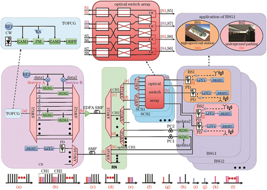
    Fig. 1. Structure diagram of multi-service layered WDM-ROF system with optional frequency millimeter wave based on optical frequency comb
    Output spectra of EAMs and PM
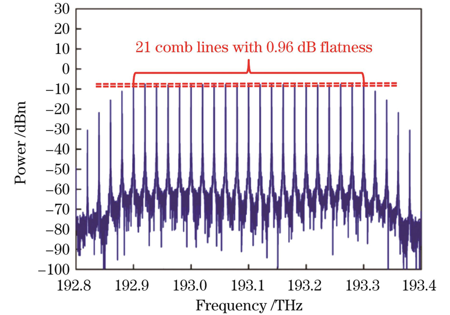
    Fig. 2. Output spectra of EAMs and PM
    Output spectra of OBPF
    Fig. 3. Output spectra of OBPF
    Output spectra of AWG2
    Fig. 4. Output spectra of AWG2
    Optical spectra of channel 1 after transmission through 20 km SMF
    Fig. 5. Optical spectra of channel 1 after transmission through 20 km SMF
    Bit error rate (BER) curves of four millimeter wave signals in base station for B-T-B, 20 km SMF and 40 km SMF transmission cases. (a) Millimeter wave signal with frequency of 35 GHz; (b) millimeter wave signal with frequency of 45 GHz; (c) millimeter wave signal with frequency of 65 GHz ; (d) millimeter wave signal with frequency of 95 GHz
    Fig. 6. Bit error rate (BER) curves of four millimeter wave signals in base station for B-T-B, 20 km SMF and 40 km SMF transmission cases. (a) Millimeter wave signal with frequency of 35 GHz; (b) millimeter wave signal with frequency of 45 GHz; (c) millimeter wave signal with frequency of 65 GHz ; (d) millimeter wave signal with frequency of 95 GHz
    Downlink data eye diagrams of 45 GHz millimeter wave for different transmission distances. (a) B-T-B; (b) 20 km SMF;
    Fig. 7. Downlink data eye diagrams of 45 GHz millimeter wave for different transmission distances. (a) B-T-B; (b) 20 km SMF;
    BER curves of uplink data in BSG1 for B-T-B, 20 km SMF and 40 km SMF transmission cases. (a) Uplink data updata1; (b) uplink data updata2
    Fig. 8. BER curves of uplink data in BSG1 for B-T-B, 20 km SMF and 40 km SMF transmission cases. (a) Uplink data updata1; (b) uplink data updata2
    Eye diagrams of uplink data updata1 for different transmission distances. (a) B-T-B; (b) 20 km SMF; (c) 40 km SMF
    Fig. 9. Eye diagrams of uplink data updata1 for different transmission distances. (a) B-T-B; (b) 20 km SMF; (c) 40 km SMF
    Millimeter wave frequency /GHzReceiving sensitivity of B-T-B /dBmReceiving sensitivity of 20 km SMF /dBmReceiving sensitivity of 40 km SMF /dBmPower cost of 20 km SMF /dBPower cost of 40 km SMF /dB
    35-11.047-10.669-10.1680.3780.879
    45-11.025-10.619-10.1320.4060.893
    65-11.013-10.581-10.1090.4320.904
    95-11.003-10.558-10.0860.4450.917
    Table 1. Receiving sensitivity and power cost of four millimeter wave signals in downlink when BER is 10-9
    Uplink dataReceiving sensitivity of B-T-B /dBmReceiving sensitivity of 20 km SMF /dBmReceiving sensitivity of 40 km SMF /dBmPower cost of 20 km SMF /dBPower cost of 40 km SMF /dB
    Updata1-18.768-18.332-17.9220.4360.846
    Updata2-18.783-18.358-17.9460.4250.837
    Table 2. Receiving sensitivity and power cost of uplink data updata1 and updata2 when BER is 10-9
    Zhenxu Lu, Peili Li, Haoran Wang. Multi‑Service Layered WDM‑ROF System with Optional Frequency Millimeter Wave Based on Optical Frequency Comb[J]. Chinese Journal of Lasers, 2023, 50(10): 1006002
    Download Citation