• Chinese Physics B
  • Vol. 29, Issue 8, (2020)
Chen Wang1、† and Da-Zhi Xu2
Author Affiliations
  • 1Department of Physics, Zhejiang Normal University, Jinhua 32004, China
  • 2School of Physics and Center for Quantum Technology Research, Beijing Institute of Technology, Beijing 100081, China
  • show less
    DOI: 10.1088/1674-1056/ab973b Cite this Article
    Chen Wang, Da-Zhi Xu. A polaron theory of quantum thermal transistor in nonequilibrium three-level systems[J]. Chinese Physics B, 2020, 29(8): Copy Citation Text show less
    Schematics of the nonequilbrium V-type three-level system in (a) the original framework and (b) the polaron framework. The three horizontal solid black lines represent the central three-level model (|u〉, u = l,r,0), and the double-arrowed solid brown line shows the coherent tunneling between two excited states |l〉 and |r〉; the rectangular left red, top-middle purple, and right blue boxes describe three thermal baths, which are characterized by temperatures Tl, Tm, and Tr, respectively; the double-arrowed solid red, purple, and blue curves describe interactions between the system and thermal baths, and the double-arrowed dashed black lines describe transitions between different states assisted by phonons in the corresponding thermal bath.
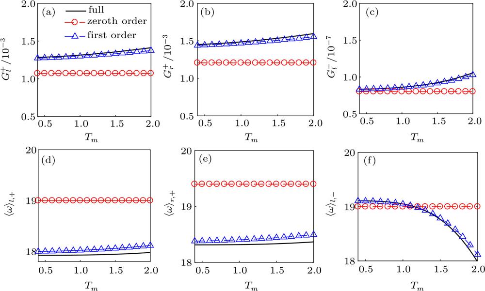
    Fig. 1. Schematics of the nonequilbrium V-type three-level system in (a) the original framework and (b) the polaron framework. The three horizontal solid black lines represent the central three-level model (|u〉, u = l,r,0), and the double-arrowed solid brown line shows the coherent tunneling between two excited states |l〉 and |r〉; the rectangular left red, top-middle purple, and right blue boxes describe three thermal baths, which are characterized by temperatures Tl, Tm, and Tr, respectively; the double-arrowed solid red, purple, and blue curves describe interactions between the system and thermal baths, and the double-arrowed dashed black lines describe transitions between different states assisted by phonons in the corresponding thermal bath.
    The transition rates (a) Gl+, (b) Gr+, (c) Gl− and the energy quanta (d) 〈ω〉l,+, (e) 〈ω〉r,+, (f) 〈ω〉l,– within the nonequilibrium NIBA scheme. The solid black lines represent the full order calculation with expressions shown in Eqs. (13b), (13c), (14a), and (14b); the dashed red lines with circles represent the zeroth order approximation in Eqs. (B8a), (B8b) (b11a), and (B11b); the dashed blue lines with up-triangles represent the first order approximation in Eqs. (B9a), (B9b), (B10a), and (B10b). The other parameters are given by εl = 1.0, εr = 0.6, Δ = 0.6, γ = 0.0002, ωc = 10, Tl = 2, and Tr = 0.4.
    Fig. 1. The transition rates (a) Gl+, (b) Gr+, (c) Gl and the energy quanta (d) 〈ωl,+, (e) 〈ωr,+, (f) 〈ωl,– within the nonequilibrium NIBA scheme. The solid black lines represent the full order calculation with expressions shown in Eqs. (13b), (13c), (14a), and (14b); the dashed red lines with circles represent the zeroth order approximation in Eqs. (B8a), (B8b) (b11a), and (B11b); the dashed blue lines with up-triangles represent the first order approximation in Eqs. (B9a), (B9b), (B10a), and (B10b). The other parameters are given by εl = 1.0, εr = 0.6, Δ = 0.6, γ = 0.0002, ωc = 10, Tl = 2, and Tr = 0.4.
    Steady state heat currents (a) Jl/γ, (b) Jm/γ, and (c) Jr/γ as a function of the coupling strength αm. The red circles are based on the Redfield scheme; the blue squares are based on the nonequilibrium noninteracting blip approximation (NIBA); the black solid line is calculated from the nonequilibrium polaron-transformed Redfield approach. The other parameters are given as εl = 1.0, εr = 0.6, Δ = 0.6, γ = 0.0002, ωc = 10, Tl = 2, Tm = 1.2, and Tr = 0.4.
    Fig. 2. Steady state heat currents (a) Jl/γ, (b) Jm/γ, and (c) Jr/γ as a function of the coupling strength αm. The red circles are based on the Redfield scheme; the blue squares are based on the nonequilibrium noninteracting blip approximation (NIBA); the black solid line is calculated from the nonequilibrium polaron-transformed Redfield approach. The other parameters are given as εl = 1.0, εr = 0.6, Δ = 0.6, γ = 0.0002, ωc = 10, Tl = 2, Tm = 1.2, and Tr = 0.4.
    (a) Average energy quanta 〈ω〉l,±, 〈ω〉r,+, and the flux rates Gl−Gm−Gr+/A and Gl+Gl−Gm−/A; (b) heat current into the middle bath Jm,NIBA/γ, the main components Jm,NIBA(a)/γ and Jm,NIBA(b)/γ; (c) heat current into the right bath Jr,NIBA/γ and the main component Jr,NIBA(a)/γ within the nonequilibrium NIBA scheme at strong coupling αm = 2. The other parameters are given by εl = 1.0, εr = 0.6, Δ = 0.6, γ = 0.0002, ωc = 10, Tl = 2, and Tr = 0.4.
    Fig. 2. (a) Average energy quanta 〈ω〉l, 〈ωr,+, and the flux rates GlGmGr+/A and Gl+GlGm/A; (b) heat current into the middle bath Jm,NIBA/γ, the main components Jm,NIBA(a)/γ and Jm,NIBA(b)/γ; (c) heat current into the right bath Jr,NIBA/γ and the main component Jr,NIBA(a)/γ within the nonequilibrium NIBA scheme at strong coupling αm = 2. The other parameters are given by εl = 1.0, εr = 0.6, Δ = 0.6, γ = 0.0002, ωc = 10, Tl = 2, and Tr = 0.4.
    (a) The globally cyclic transition contributed by the Gl±Gm±Gr∓/A, and the locally conditional transitions contributed by (b) Gm−Gl+Gl−/A, (c) Gm+Gr+Gr−/A, (d) Gr−Gl+Gl−/A, and (e) Gl−Gr+Gr−/A within the nonequilibrium NIBA scheme, respectively. The horizontal solid black line at top represents |0〉; two horizontal solid black lines at bottom describe renormalized energy levels |l(r)〉 with the energies El(r) = εl(r) – Σk|gk,m|2/ωk. The other symbols are the same as those in Fig. 1.
    Fig. 3. (a) The globally cyclic transition contributed by the Gl±Gm±Gr/A, and the locally conditional transitions contributed by (b) GmGl+Gl/A, (c) Gm+Gr+Gr/A, (d) GrGl+Gl/A, and (e) GlGr+Gr/A within the nonequilibrium NIBA scheme, respectively. The horizontal solid black line at top represents |0〉; two horizontal solid black lines at bottom describe renormalized energy levels |l(r)〉 with the energies El(r) = εl(r)Σk|gk,m|2/ωk. The other symbols are the same as those in Fig. 1.
    Heat amplification factor as a function of system–middle bath coupling strength αm in low (Tl = 0.5, Tr = 0.4) and high (Tl = 2, Tr = 0.4) temperature bias regimes, with maxTr<Tm<Tl{βr} the maximal value of βr by tuning the temperature of the middle bath Tm between Tr and Tl. The other parameters are given by εl = 1.0, εr = 0.6, Δ = 0.6, γ = 0.0002, and ωc = 10.
    Fig. 4. Heat amplification factor as a function of system–middle bath coupling strength αm in low (Tl = 0.5, Tr = 0.4) and high (Tl = 2, Tr = 0.4) temperature bias regimes, with maxTr<Tm<Tl{βr} the maximal value of βr by tuning the temperature of the middle bath Tm between Tr and Tl. The other parameters are given by εl = 1.0, εr = 0.6, Δ = 0.6, γ = 0.0002, and ωc = 10.
    (a) Heat amplification factor βr as a function of the middle bath temperature Tm with various system–middle bath coupling strength αm; (b) three steady state heat currents Ju/γ (u = l,m,r) as a function of Tm with the coupling strength αm = 4, and the inset is the zoom in view of Jm/γ; (c) the 3D view of the heat amplification factor βr by tuning Tm and αm. The other parameters are given by εl = 1.0, εr = 0.6, Δ = 0.6, γ = 0.0002, ωc = 10, Tl = 2, and Tr = 0.4.
    Fig. 5. (a) Heat amplification factor βr as a function of the middle bath temperature Tm with various system–middle bath coupling strength αm; (b) three steady state heat currents Ju/γ (u = l,m,r) as a function of Tm with the coupling strength αm = 4, and the inset is the zoom in view of Jm/γ; (c) the 3D view of the heat amplification factor βr by tuning Tm and αm. The other parameters are given by εl = 1.0, εr = 0.6, Δ = 0.6, γ = 0.0002, ωc = 10, Tl = 2, and Tr = 0.4.
    Steady state behaviors as a function of the middle bath temperature Tm within the nonequilibrium NIBA at strong coupling (αm = 4): (a) transition rates Gu±(u=l,m,r) in Eqs. (13a)–(13c), and (b) average energy quanta 〈ω〉u,± (u = l,r) in Eqs. (14a) and (14b); (c) heat current Jm,NIBA and its main components in Eqs. (20a) and(20b), and (d) comparison of the approximate amplification factor βr,NIBA with βr. (e) and (f) Schematic illustrations of flow components Jm,NIBA(a) and Jm,NIBA(b). The other parameters are the same as those in Fig. 5.
    Fig. 6. Steady state behaviors as a function of the middle bath temperature Tm within the nonequilibrium NIBA at strong coupling (αm = 4): (a) transition rates Gu±(u=l,m,r) in Eqs. (13a)–(13c), and (b) average energy quanta 〈ωu (u = l,r) in Eqs. (14a) and (14b); (c) heat current Jm,NIBA and its main components in Eqs. (20a) and(20b), and (d) comparison of the approximate amplification factor βr,NIBA with βr. (e) and (f) Schematic illustrations of flow components Jm,NIBA(a) and Jm,NIBA(b). The other parameters are the same as those in Fig. 5.
    (a) Heat amplification factor βr with various coupling strengthes αm, and (b) steady state heat currents with αm = 0.02 as a function of Tm, the inset is the zoom-in view of Jm/γ. The other parameters are the same as those in Fig. 5.
    Fig. 7. (a) Heat amplification factor βr with various coupling strengthes αm, and (b) steady state heat currents with αm = 0.02 as a function of Tm, the inset is the zoom-in view of Jm/γ. The other parameters are the same as those in Fig. 5.
    (a) Schematic illustration of quantum thermal transport in the three-level system (|±〉η and |0〉) contacting with the l-th and m-th thermal baths; (b) steady state heat currents by modulating the temperature bias Tl – Tm, which have different order approximations with αm = 0.02; (c) steady state heat currents by tuning the temperature bias Tl – Tm with various system–middle bath coupling strengthes. The temperature of the left thermal bath is Tl = 2, and the other parameters are the same as those in Fig. 5.
    Fig. 8. (a) Schematic illustration of quantum thermal transport in the three-level system (|±〉η and |0〉) contacting with the l-th and m-th thermal baths; (b) steady state heat currents by modulating the temperature bias TlTm, which have different order approximations with αm = 0.02; (c) steady state heat currents by tuning the temperature bias TlTm with various system–middle bath coupling strengthes. The temperature of the left thermal bath is Tl = 2, and the other parameters are the same as those in Fig. 5.
    Chen Wang, Da-Zhi Xu. A polaron theory of quantum thermal transistor in nonequilibrium three-level systems[J]. Chinese Physics B, 2020, 29(8):
    Download Citation