• Matter and Radiation at Extremes
  • Vol. 8, Issue 5, 055601 (2023)
T. A. Shelkovenko, I. N. Tilikina), A. V. Oginov, A. R. Mingaleev, V. M. Romanova, and S. A. Pikuz
Author Affiliations
  • P. N. Lebedev Physical Institute of the Russian Academy of Sciences, Moscow, Russia
  • show less
    DOI: 10.1063/5.0146820 Cite this Article
    T. A. Shelkovenko, I. N. Tilikin, A. V. Oginov, A. R. Mingaleev, V. M. Romanova, S. A. Pikuz. Methods of controlled formation of instabilities during the electrical explosion of thin foils[J]. Matter and Radiation at Extremes, 2023, 8(5): 055601 Copy Citation Text show less

    Abstract

    The results of a study of the electrical explosion of aluminum foils with an artificial periodic surface structure created by laser engraving are presented. Experiments were carried out on pulsed high-current generators BIN (270 kA, 300 kV, 100 ns) and KING (200 kA, 40 kV, 200 ns) with Al foil of thicknesses 16 and 4 μm, respectively. Images of the exploded foils were recorded by point projection radiography in the radiation from hybrid X-pinches. It is found that the application of an artificial periodic structure to the foil leads to a much more uniform and well-defined periodic structure of the exploded foil. Images recorded in the UV range using a microchannel-plate-intensified detector show that the radiation from a surface-modified foil is more uniform along the entire length and width of the foil than that from a foil without modification.

    I. INTRODUCTION

    Exploding flat foils are used as detonators,1,2 as fast switches in pulsed current generators,3,4 to generate shock waves,5 and in other applications. One promising application may be the use of exploding foils as a source of intense UV radiation.6,7 Foil liners are also considered promising as loads in inertial confinement fusion research instead of wire arrays.8,9 The control of instabilities arising during the explosion of foils is an important condition for their successful application.

    Using point-projection radiography, we have shown experimentally that initial structures, periodic in one or two directions, are present in exploding foils.10–13 These experiments have also shown that the energy deposited in the foil depends on the mutual orientation of the foil and the current flowing through it, which, of course, affects the structure of the exploded foil.10 Owing to the limited set of thin foils from different materials of different thicknesses that are available for use, the range of variant structures that are available is also quite small. It can be expanded by application to the foil surface of an artificial periodic structure with a given direction and scale.12 After studying how such structures affect the explosion mode, it is possible to choose the optimal variant of the foil load for a particular application. When using metal liners for inertial fusion, for example, adding an external structure to the foil could inhibit the development of instabilities during the foil explosion.14–16 For creating powerful generators of high-voltage pulses, shock wave generation, and detonators, the most important factor is the rate of disintegration of the exploded foil.1–5 This requires an external influence, which leads to faster growth of instabilities in the exploded foil. There may be many similar applications, each of which will require specific explosion conditions and a corresponding foil structure.

    This paper presents experimental data obtained during the explosion of modified flat aluminum foils on the BIN and KING generators. The results presented here show that it is possible to choose a modification of the foil that leads to the appearance of well-formed periodic instabilities in the exploded foil. The paper also describes the effect of these structures on the UV radiation from the exploded foil.

    II. EXPERIMENTAL SETUP AND DIAGNOSTICS

    A detailed description of experiments with foil exposed to laser pulses is given in Ref. 12. In the present paper, we will give just a brief description of the experiment and diagnostics. In experiments to study the core structure of exploded Al foils, the pulsed high-voltage generator BIN at the P. N. Lebedev Physical Institute was used [Fig. 1(a)]. The structure of Al foils of thickness 16 μm, width 1.0–1.5 mm, and length 10 mm was studied. This type of foil is an ordinary kitchen foil, which is a very complex alloy. Special spectroscopic experiments were carried out to determine the composition and yielded the following as the main components of the alloy: Al 84.3%, Ag 7.4%, Ac 2.6%, Co 2.3%, O 1.4%, Fe 0.6%, Cu 0.5%, and Si 0.5%, with traces of other elements. Foil with a thickness of 4 μm specially obtained for scientific purposes consists mainly of Al 97.6% and Si 2%, with traces of other elements.

    (a) Signals of the total discharge current, the current through the foil, and the x-ray pulse in the experiment on the BIN generator. (b) Signals of the total discharge current (the current through the foil) and UV radiation (E > 10 eV) from the exploded foil in experiments on the KING generator.

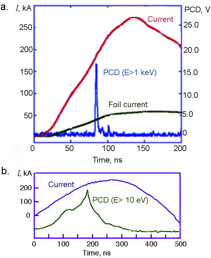
    Figure 1.(a) Signals of the total discharge current, the current through the foil, and the x-ray pulse in the experiment on the BIN generator. (b) Signals of the total discharge current (the current through the foil) and UV radiation (E > 10 eV) from the exploded foil in experiments on the KING generator.

    In Ref. 12, it was shown that when the foil is modified by the application of grooves, the initial structure of the foil plays an important role. Therefore, in these experiments on the BIN generator, only foil of thickness of 16 μm was used, having a one-dimensional initial periodic structure with a scale of 30 μm. In the experiments on the BIN generator, the foil was placed in a return current circuit, and the current through the foil was measured by a Rogowski coil and varied from 70 to 80 kA [Fig. 1(a)].

    Point-projection radiography was used to study the structure of exploding foils [Fig. 2(a)],17–20 with hybrid X-pinches being used as the radiation source.18 The response time of the X-pinch was determined by the signal of a photoconducting detector (PCD) with a 10 μm thick Be filter [Fig. 1(a)]. Hybrid X-pinches using Mo wire of diameter 25 μm and length 3 mm were used as the main load of the generator [Fig. 2(a)(4)], while the foil was placed in a return current circuit [Fig. 2(a)(5)]. Hybrid X-pinches consist of an exploding thin wire of short length located between refractory electrodes. When a current flows through the wire, the wire explodes and pinches, forming an intense point source of soft x-ray radiation. Note that the interelectrode gap on the BIN generator decreases by about 2 mm when the chamber is pumped out, and so the initial length of the hybrid X-pinch wire should be at least 3 mm. Images of exploded foils were recorded by Fuji TR x-ray imaging plates with a 12.5 μm thick titanium foil filter with 6 μm Mylar. At the 7.8× magnification used in these experiments, the spatial resolution as determined by the resolution of the plates and that of the scanner was about 4 μm for a radiation energy of 4 keV.

    (a) Schematic of experiments to study the structure of an exploded foil on the BIN generator. (b) Schematic of experiments to study UV radiation from an exploded foil on the KING generator. (c) Schematic of experiments to image a test object in UV radiation from an exploded foil on the KING generator. Key: (1) cathode plate; (2) return current post; (3) anode plate; (4) hybrid X-pinch; (5) thin foil; (6) filter; (7) imaging plate; (8) PCD; (9) pinhole camera; (10) MCP; (11) test object (a mesh with a wire diameter of 200 μm). y and x are the distances determining the magnifications in each scheme: x = 45 cm, y = 305 cm; y′ = 57 cm, x′ = 68 cm; y″ = 57 cm, x″ = 35 mm.

    Figure 2.(a) Schematic of experiments to study the structure of an exploded foil on the BIN generator. (b) Schematic of experiments to study UV radiation from an exploded foil on the KING generator. (c) Schematic of experiments to image a test object in UV radiation from an exploded foil on the KING generator. Key: (1) cathode plate; (2) return current post; (3) anode plate; (4) hybrid X-pinch; (5) thin foil; (6) filter; (7) imaging plate; (8) PCD; (9) pinhole camera; (10) MCP; (11) test object (a mesh with a wire diameter of 200 μm). y and x are the distances determining the magnifications in each scheme: x = 45 cm, y = 305 cm; y′ = 57 cm, x′ = 68 cm; y″ = 57 cm, x″ = 35 mm.

    A portable KING generator (200 kA, 40 kV, 220 ns) was used in experiments to study the radiation from exploded foils.21,22 In these experiments, the foil was placed in the generator diode as the main load [Fig. 2(b)(4)]. The radiation from the exploded foils was recorded by a diamond detector (PCD) with a mesh filter with 36% transmission. An Ni mesh was used as a gray filter to reduce the signal level and for partial protection of the crystal surface and electrodes from intense UV radiation [Fig. 2(b)]. Images of the exploded Al foils with thicknesses 4 and 16 μm in the UV range were recorded using pinhole cameras with a diameter of 200 μm and a recorder with a four-frame microchannel plate (MCP) camera with a time resolution of 5 ns. The images were recorded with a magnification of 1:1.2 [Fig. 2(b)]. The cutoff energy of the radiation determined by the diameter of the pinhole camera and the geometry of the experiment was about 40 eV.

    The Al foil was processed in air using a commercially available apparatus based on a high-contrast Yb pulsed fiber laser with a wavelength λ = 1.06 μm, a focal spot of 40 μm, a pulse duration of 120 ns and an average power of 30 W. To create the grooves, a single laser operating mode was used, with a pulse energy equal to 80% of the maximum energy.12

    Note that in these experiments, the initial structure of the foil was also taken into account. All foil explosion experiments were carried out with the foil’s initial structure located parallel and perpendicular to the direction of the current. Foil processing was carried out in the same way for the two directions of the foil’s initial structure. To obtain more reliable results, all experiments were repeated at least three times for each time of image registration.

    III. EXPERIMENTAL RESULTS

    A. Structure of exploding foils

    Experiments to study the structure of exploded foils with pits and holes were carried out on the BIN generator. Pits were made in one laser pass at 80% power and holes at 100% power on 16 μm thick Al foil. Photographs of the pits taken with a JEOL 7001F scanning electron microscope (SEM) with a field emission gun are shown in Fig. 3. It can be seen that the size of the perforation area (the pit together with the transition area, which is a metal rim around it) averages 60–65 μm. The depth of the pits relative to the foil surface is ∼2 μm. This follows from the fact that in two passes at a given laser power, a 4 μm thick foil is burned through. The height of the rim is difficult to estimate. Roughly, we can assume that all material from the pit forms the rim. Based on the fact that the outer diameter of the rim is 70 μm and the inner diameter is 50 μm, the height of the rim is equal to or less than 2 μm. The diameter of the pit varies within 10 μm. The distance between the centers of the pits, which is the step of the applied disturbances, also varies, from 90 to 110 μm. Similar estimates for the grooves also gave a depth of about 2 μm.12

    Photographs of the structure of Al foil after laser exposure, as a result of which depressions of diameter 50 μm and depth 2 μm are formed, applied with a scale of about 100 μm.

    Figure 3.Photographs of the structure of Al foil after laser exposure, as a result of which depressions of diameter 50 μm and depth 2 μm are formed, applied with a scale of about 100 μm.

    For the first time, an artificial structure in the form of pits was used together with grooves engraved with a laser engraving machine parallel and perpendicular to the foil’s initial structure and the current (Fig. 4). It can be seen from sections 2–4 in Fig. 4(b) that grooves aligned perpendicular to the foil’s initial structure slow down the development of core instabilities by about 30% compared with the case of an exploded foil without surface modification. Slowing down the development of instabilities in exploded foil can be of great importance for the use of foil liners in inertial fusion and other applications. From section 1 in Fig. 4, it can be seen that grooves parallel to the foil’s initial structure cause the foil material to contract and form randomly arranged absorption bands of the order of 0.3 mm in size.

    (a) Radiograph of an exploded Al foil with sections 1–5 on which various modifications had been made: (1) a section with grooves of width 50 μm, made with a 100 μm scale (the distance between the centers of the grooves) parallel to the foil’s initial structure in the X direction; (2) and (4) sections of exploded foil without modification; (3) a section with grooves of width 50 μm, made through 100 μm perpendicular to the foil’s initial structure in the Y direction; (5) a section with modification by pits of diameter 50 μm and scales along the Y and X axes of 50 μm. The foil’s initial structure is located in the X direction, i.e., parallel to the current. (b) Transmission curve for all sections of the exploded foil.

    Figure 4.(a) Radiograph of an exploded Al foil with sections 1–5 on which various modifications had been made: (1) a section with grooves of width 50 μm, made with a 100 μm scale (the distance between the centers of the grooves) parallel to the foil’s initial structure in the X direction; (2) and (4) sections of exploded foil without modification; (3) a section with grooves of width 50 μm, made through 100 μm perpendicular to the foil’s initial structure in the Y direction; (5) a section with modification by pits of diameter 50 μm and scales along the Y and X axes of 50 μm. The foil’s initial structure is located in the X direction, i.e., parallel to the current. (b) Transmission curve for all sections of the exploded foil.

    In the same shot, a mesh of pits of diameter 50 μm (the pits have the parameters from Fig. 3), applied every 50 μm, causes the formation of a sinusoidal periodic instability with a scale of about 50 μm in the exploded foil [section 5 in Fig. 4(b)]. This structure is evenly distributed over the dotted surface of the exploded foil. Section 5 in Fig. 4 shows that the average absorption in this part of the foil is slightly less and the deviation from the average absorption value is greater than in the foil without modification.

    In Figs. 46, transmission curves are shown for the entire surface of the exploded foils, excluding 100 μm wide zones near both edges (in the Y direction) of the foils.

    Radiograph of an exploded Al foil with sections 1–3 on which modifications had been made in the form of pits of diameter 50 μm with various scales (average distance between pits) along the Y and X axes: (1) 50 μm (Y), 100 μm (X); (2) 100 μm (Y), 50 μm (X); (3) 100 μm (Y), 100 μm (X); (4) foil without modification. (b) Transmission curve for sections 1–4.

    Figure 5.Radiograph of an exploded Al foil with sections 1–3 on which modifications had been made in the form of pits of diameter 50 μm with various scales (average distance between pits) along the Y and X axes: (1) 50 μm (Y), 100 μm (X); (2) 100 μm (Y), 50 μm (X); (3) 100 μm (Y), 100 μm (X); (4) foil without modification. (b) Transmission curve for sections 1–4.

    (a) Photograph of pits taken with ×15 magnification using an optical microscope. (b) Radiograph of an exploded Al foil with sections 1, 3, and 5 on which a modification had been made in the form of pits of diameter 50 μm with various scales (average distance between pits) along the Y and X axes: (1) 50 μm (Y), 100 μm (X); (3) 100 μm (Y), 50 μm (X); (5) 100 μm (Y), 100 μm (X). Sections 2 and 4 are without modification. The scale of instabilities is 90 μm in section 1, 45 µm in section 3, and 90 µm in section 5. (c) Transmission curve for sections 1–5.

    Figure 6.(a) Photograph of pits taken with ×15 magnification using an optical microscope. (b) Radiograph of an exploded Al foil with sections 1, 3, and 5 on which a modification had been made in the form of pits of diameter 50 μm with various scales (average distance between pits) along the Y and X axes: (1) 50 μm (Y), 100 μm (X); (3) 100 μm (Y), 50 μm (X); (5) 100 μm (Y), 100 μm (X). Sections 2 and 4 are without modification. The scale of instabilities is 90 μm in section 1, 45 µm in section 3, and 90 µm in section 5. (c) Transmission curve for sections 1–5.

    Since an interesting result had already been obtained in the first experiments with pits applied to the foil, it was decided to perform a more detailed study of the features of the formation of instabilities in foils with a pit structure. For this purpose, pits of diameter 50 μm with various scales along the X and Y axes were applied to 16 μm thick Al foil. It can be seen from Fig. 5 that the amplitude of instabilities in the case of foils with an applied pit structure is two [sections 2 and 3 in Fig. 5(b)] or three [section 1 in Fig. 5(b)] times greater than the amplitude of instabilities observed in an exploded foil without modification [section 4 in Fig. 5(b)].

    In the next experiment, a mesh (i.e., a 2D array) of pits with scales of 100 μm along the Y and X axes was applied to the foil at different laser powers, namely, 80%, 70%, and 60% of maximum power. For the meshes created at 70% and 80% of maximum power, the scale and amplitude of instabilities formed in the exploded foil were comparable. The mesh created at 60% of maximum power did not have a noticeable effect on the formation of instabilities in the exploded foil.

    In the final experiment, the foil was perforated with a 2D array of holes with the same scale as in the experiment with pits. The amplitude and scale of instabilities formed in the exploded foil were similar to those of the instabilities formed in the experiments with pits. The average absorption in the areas modified by pits and in the areas modified by holes was noticeably less than the absorption in an exploded foil without modification (Figs. 5 and 6). In the modified areas, regions with a well-defined periodic structure were formed when the foil exploded. With pit or hole modification of the foil in the X direction with a scale of 50 μm, the instability scale in the exploded foil was ∼45 μm, whereas with modification by perforations with a scale of 100 μm, the instability scale was about 90 μm. A difference of 5–10 μm can be explained by inaccurate reproduction of the specified scale during application of pits or holes, as can be seen from Fig. 3.

    These experiments have shown that when the foil modification is in the form of pits or holes, there is no noticeable effect of the foil’s initial structure on the structure of the exploded foil. This is probably due to the more significant influence of the foil modification on the amplitude and scale of instabilities formed during the explosion of the foil compared with the influence of the foil’s initial structure at high currents.

    B. UV radiation from exploded foils

    During the experiments, it was assumed that the occurrence of a well-structured instability with the same scale over the entire modified surface of the foil can lead to more uniform UV radiation during the explosion of the foil. The creation of a homogeneous UV source of large area is an important condition for practical applications. To confirm the above assumption, experiments were carried out on the KING generator to investigate the UV radiation from an exploded foil with pit and hole modification over the entire surface of the foil. The radiation was recorded by four-frame recorder with an MCP, using the scheme shown in Fig. 2(b) (the fourth frame of the recorder did not work). The recorder provided 5 ns time resolution, and the spatial resolution was provided by a pinhole camera.

    It was found to be very difficult to use 16 μm thick Al foils in experiments on the KING generator. Probably because of the low voltage of the generator (with a maximum value of 40 kV), foil breakdown was observed in just one of 10–15 shots. As a result, it was not possible to obtain a complete picture of the dynamics of the radiation by the foils. Foils of thickness 4 μm did exhibit breakdown regularly, and experiments have shown that the dynamics of UV radiation is similar for both 16 and 4 μm thick foils. The explosion stages in the case of a 16 μm thick foil lagged behind those of a thin foil by about 25 ns.

    Figure 7 shows characteristic pinhole images in the UV radiation from exploded Al foil without modification, while Fig. 8 shows images from Al foil with surface modification by pits. During the explosion of the foil without modification, the same result was obtained as in the experiments described in Ref. 22. In early frames, intense radiation from the edges of the foil is visible, and in later frames, additional radiation is emitted from the central part of the foil, the intensity of which increases over time. In Ref. 22, it was shown that after breakdown of the central part of the foil, a plasma column with higher values of the plasma parameters is formed. This formation is called a precursor, by analogy with the precursor in wire arrays. Figure 7 shows the uneven development of the breakdown of the foil along its length, with more intense radiation from the precursor on the cathode side and more intense radiation from the edges of the foil on the anode side. An image of an exploded foil with pits of diameter 50 μm previously applied to its surface with scales along the Y and X axes of 100 and 50 μm, respectively, is shown in Fig. 8. The images were recorded at approximately the same times as in the case of the foil without modification. The image in UV radiation from the exploded foil with surface modification remains almost uniform along both its width and length for more than 15 ns. This uniformity of the radiation is recorded within a spatial resolution of about 200 μm. On the radiation intensity curve, weak precursor radiation is observed only in the close vicinity of the cathode.

    (a) Pinhole images of exploded 4 μm thick Al foil without modification obtained in the UV range with radiation energy above 40 eV with a time resolution of 5 ns. The instants at the beginning of each frame are indicated at the top. (b) Intensity curves at the locations marked by lines 1–3 in (a).

    Figure 7.(a) Pinhole images of exploded 4 μm thick Al foil without modification obtained in the UV range with radiation energy above 40 eV with a time resolution of 5 ns. The instants at the beginning of each frame are indicated at the top. (b) Intensity curves at the locations marked by lines 1–3 in (a).

    (a) Pinhole images of exploded Al foil with surface modification by pits of diameter 50 μm and scale (distance between pit centers) of 100 μm along both the X and Y axes. The images were recorded in the UV range with a time resolution of 5 ns. The instants of the beginning of each frame are indicated at the top. The direction of the current through the foil is shown by the arrow. (b) Intensity curves at the locations marked by lines 1–3 in (a).

    Figure 8.(a) Pinhole images of exploded Al foil with surface modification by pits of diameter 50 μm and scale (distance between pit centers) of 100 μm along both the X and Y axes. The images were recorded in the UV range with a time resolution of 5 ns. The instants of the beginning of each frame are indicated at the top. The direction of the current through the foil is shown by the arrow. (b) Intensity curves at the locations marked by lines 1–3 in (a).

    Thus, the application of an artificial pit structure on the foil leads to a much more uniform radiation from the exploded foil in the UV range. Figure 9 shows an example of the use of an exploded foil as a source of UV radiation. For this purpose, a mesh of wires of diameter 200 mm was placed in the path of the foil radiation, as shown in Fig. 2(b). Such a mesh is a good 2D test object, demonstrating radiation intensity and spatial resolution in two directions.

    Pinhole images of a mesh with a wire diameter of 200 μm, obtained in the UV radiation from an exploded Al foil: (a) foil without modification (b) foil with modification of the entire surface by the application of pits of diameter 50 μm and scale (distance between pit centers) of 100 μm along both the X and Y axes. The mesh image was obtained with 1.6× magnification. The direction of the current through the foil is shown by the arrows. The moments of the beginning of the frame are indicated at the top.

    Figure 9.Pinhole images of a mesh with a wire diameter of 200 μm, obtained in the UV radiation from an exploded Al foil: (a) foil without modification (b) foil with modification of the entire surface by the application of pits of diameter 50 μm and scale (distance between pit centers) of 100 μm along both the X and Y axes. The mesh image was obtained with 1.6× magnification. The direction of the current through the foil is shown by the arrows. The moments of the beginning of the frame are indicated at the top.

    Figure 9(b) shows that the mesh images obtained in the radiation from the exploded foil with surface modification are uniform along both the length and width of the foil (in the range 200 μm), whereas the mesh images obtained in the radiation from the foil without modification are uneven along both directions [Fig. 9(a)]. Figure 1(b) shows the typical UV radiation signal obtained on the KING generator during the explosion of 4 μm thick Al foil. It can be seen that at the times of 30–45 ns, when the above images were recorded, the radiation intensity was very low. However, the intensity of the UV radiation was quite sufficient to obtain an intense image of the mesh using the MCP through a pinhole camera with a diameter of 200 μm, located at distances of 57 or 35 cm.

    Practically similar results were obtained when the foil was perforated by holes with the same scale as the pits. Thus, when exploded foils are intended for use as a source of UV radiation, laser-engraved holes can be used for modification, which for very thin foils is sometimes more convenient than the application of pits.

    IV. DISCUSSION

    The initial structure of Al foils was recorded by point-projection radiography, sensitive to the density of the object and the length of the path through it. No significant changes in the thickness of the foil along either its length or its width were recorded. Probably the initial structure of the foil was associated with local changes in density arising during its manufacture. In Refs. 10–13, it was shown that the orientation of the foil’s initial structure relative to the applied current affects the energy deposited in the foil and the resulting structure of the exploded foil. From this, we can suppose that the changes in density could lead to local changes in resistance, and thus to periodic changes in current and an increased rate of instability.

    For 16 μm thick Al foil, the application of 2 μm deep grooves perpendicular to the foil’s initial structure and to the current direction increases the current beneath the grooves and decreases the current in the regions between them, causing oscillatory deviations in the flow of current both along and across the foil. Under these conditions, both oscillations are damped. This leads to a decrease in the rate of growth of the amplitude of instabilities over time, which we have recorded in experiments.

    Pits or holes periodically applied in two perpendicular directions probably have a stronger effect on the development of instability in the exploded foil than a small periodic change in the amplitude of the current flowing through the foil. This appears to explain why we have not recorded any significant effect of the initial structure on the structure of the exploded foil.

    V. CONCLUSIONS

    Experiments have shown that surface modification of a foil may be used to control the occurrence and dynamics of instabilities in the exploded foil. For example, preliminary laser engraving of the foil surface in the form of grooves in a direction perpendicular to the current and to the foil’s initial structure leads to a noticeable smoothing of inhomogeneities, which is an important factor in achieving high load compression parameters for inertial fusion.

    Modification of the foil in the form of periodically applied pits or holes causes the formation of periodic instabilities with a more pronounced amplitude than in a foil without modification. The scale of the instabilities formed during explosion of the foil is close to the scale of the applied pits or holes. The application to the surface of the foil of an artificial periodic structure in the form of pits leads to much more uniform UV radiation from the foil along its length and width. The explosion of surface-modified foils can be used to provide a uniform source of UV radiation of large extent for a number of possible applications, including for example, the disinfection of large objects.

    ACKNOWLEDGMENTS

    Acknowledgment. The experiments described here are supported by the Russian Science Foundation, Project No. 19-79-30086-P.

    References

    [1] L.Smilowitz, L.Smilowitz, D.Remelius, N.Suvorova, P.Bowlan, D.Oschwald, B. and, D.Remelius, L.Smilowitz, D.Remelius, N.Suvorova, P.Bowlan, D.Oschwald, B. and, N.Suvorova, L.Smilowitz, D.Remelius, N.Suvorova, P.Bowlan, D.Oschwald, B. and, P.Bowlan, L.Smilowitz, D.Remelius, N.Suvorova, P.Bowlan, D.Oschwald, B. and, D.Oschwald, L.Smilowitz, D.Remelius, N.Suvorova, P.Bowlan, D.Oschwald, B. and, B. F.Henson. Finding the ‘lost-time’ in detonator function. Appl. Phys. Lett., 114, 104102(2019).

    [2] P. J.Rae, J.Rae P., A.Feagin T., E. and, T. A.Feagin, J.Rae P., A.Feagin T., E. and, E. M.Heatwole. Investigating the minimum post-burst energy required to function an exploding bridgewire detonator. J. Appl. Phys., 128, 033301(2020).

    [3] V. S.Sedoi, S.Sedoi V., A.Mesyats G., I.Oreshkin V., V.Valevich V., L. and, G. A.Mesyats, S.Sedoi V., A.Mesyats G., I.Oreshkin V., V.Valevich V., L. and, V. I.Oreshkin, S.Sedoi V., A.Mesyats G., I.Oreshkin V., V.Valevich V., L. and, V. V.Valevich, S.Sedoi V., A.Mesyats G., I.Oreshkin V., V.Valevich V., L. and, L. I.Chemezova. The current density and the specific energy input in fast electrical explosion. IEEE Trans. Plasma Sci., 27, 845(1999).

    [4] V. A.Burtsev, A.Burtsev V., V.Kalinin N., A. and, N. V.Kalinin, A.Burtsev V., V.Kalinin N., A. and, A. V.Luchinskii. Electric Explosion of Conductors and its Application in Electrophysical Plants(1990).

    [5] T.Mihara, T.Mihara, N.Matsuo, M.Otsuka, S.Itoh and, N.Matsuo, T.Mihara, N.Matsuo, M.Otsuka, S.Itoh and, M.Otsuka, T.Mihara, N.Matsuo, M.Otsuka, S.Itoh and, S.Itoh. Study on metal foil explosion using high current. Proc. SPIE, 7522, 75222A(2010).

    [6] V. V.Aleksandrov, V.Aleksandrov V., M.Basko M., V.Branitskii A., V.Grabovsky E., N.Gritsuk A., N.Mitrofanov K., M.Oleinik G., V.Sasorov P., I. and, M. M.Basko, V.Aleksandrov V., M.Basko M., V.Branitskii A., V.Grabovsky E., N.Gritsuk A., N.Mitrofanov K., M.Oleinik G., V.Sasorov P., I. and, A. V.Branitskii, V.Aleksandrov V., M.Basko M., V.Branitskii A., V.Grabovsky E., N.Gritsuk A., N.Mitrofanov K., M.Oleinik G., V.Sasorov P., I. and, E. V.Grabovsky, V.Aleksandrov V., M.Basko M., V.Branitskii A., V.Grabovsky E., N.Gritsuk A., N.Mitrofanov K., M.Oleinik G., V.Sasorov P., I. and, A. N.Gritsuk, V.Aleksandrov V., M.Basko M., V.Branitskii A., V.Grabovsky E., N.Gritsuk A., N.Mitrofanov K., M.Oleinik G., V.Sasorov P., I. and, K. N.Mitrofanov, V.Aleksandrov V., M.Basko M., V.Branitskii A., V.Grabovsky E., N.Gritsuk A., N.Mitrofanov K., M.Oleinik G., V.Sasorov P., I. and, G. M.Oleinik, V.Aleksandrov V., M.Basko M., V.Branitskii A., V.Grabovsky E., N.Gritsuk A., N.Mitrofanov K., M.Oleinik G., V.Sasorov P., I. and, P. V.Sasorov, V.Aleksandrov V., M.Basko M., V.Branitskii A., V.Grabovsky E., N.Gritsuk A., N.Mitrofanov K., M.Oleinik G., V.Sasorov P., I. and, I. N.Frolov. Investigation of X-ray self-emission of plasma of targets heated by high-power pulses of soft X-ray radiation. Plasma Phys. Rep., 47, 669(2021).

    [7] S. A.Pikuz, A.Pikuz S., A.Shelkovenko T., N.Tilikin I., A.Bolkhovitinov E., A.Kologrivov A., R.Mingaleev A., M.Romanova V., A. and, T. A.Shelkovenko, A.Pikuz S., A.Shelkovenko T., N.Tilikin I., A.Bolkhovitinov E., A.Kologrivov A., R.Mingaleev A., M.Romanova V., A. and, I. N.Tilikin, A.Pikuz S., A.Shelkovenko T., N.Tilikin I., A.Bolkhovitinov E., A.Kologrivov A., R.Mingaleev A., M.Romanova V., A. and, E. A.Bolkhovitinov, A.Pikuz S., A.Shelkovenko T., N.Tilikin I., A.Bolkhovitinov E., A.Kologrivov A., R.Mingaleev A., M.Romanova V., A. and, A. A.Kologrivov, A.Pikuz S., A.Shelkovenko T., N.Tilikin I., A.Bolkhovitinov E., A.Kologrivov A., R.Mingaleev A., M.Romanova V., A. and, A. R.Mingaleev, A.Pikuz S., A.Shelkovenko T., N.Tilikin I., A.Bolkhovitinov E., A.Kologrivov A., R.Mingaleev A., M.Romanova V., A. and, V. M.Romanova, A.Pikuz S., A.Shelkovenko T., N.Tilikin I., A.Bolkhovitinov E., A.Kologrivov A., R.Mingaleev A., M.Romanova V., A. and, A. A.Rupasov. Study of SXR/EUV radiation of exploded foils and wires with spectral, spatial and temporal resolution simultaneously on KING electric discharge facility. Plasma Sources Sci. Technol., 30, 115012(2021).

    [8] V. L.Kantsyrev, L.Kantsyrev V., S.Chuvatin A., S.Safronova A., I.Rudakov L., A.Esaulov A., L.Velikovich A., I.Shrestha, A.Astanovitsky, C.Osborne G., V.Shlyaptseva V., E.Weller M., S.Keim, A.Stafford, M.Cooper and, A. S.Chuvatin, L.Kantsyrev V., S.Chuvatin A., S.Safronova A., I.Rudakov L., A.Esaulov A., L.Velikovich A., I.Shrestha, A.Astanovitsky, C.Osborne G., V.Shlyaptseva V., E.Weller M., S.Keim, A.Stafford, M.Cooper and, A. S.Safronova, L.Kantsyrev V., S.Chuvatin A., S.Safronova A., I.Rudakov L., A.Esaulov A., L.Velikovich A., I.Shrestha, A.Astanovitsky, C.Osborne G., V.Shlyaptseva V., E.Weller M., S.Keim, A.Stafford, M.Cooper and, L. I.Rudakov, L.Kantsyrev V., S.Chuvatin A., S.Safronova A., I.Rudakov L., A.Esaulov A., L.Velikovich A., I.Shrestha, A.Astanovitsky, C.Osborne G., V.Shlyaptseva V., E.Weller M., S.Keim, A.Stafford, M.Cooper and, A. A.Esaulov, L.Kantsyrev V., S.Chuvatin A., S.Safronova A., I.Rudakov L., A.Esaulov A., L.Velikovich A., I.Shrestha, A.Astanovitsky, C.Osborne G., V.Shlyaptseva V., E.Weller M., S.Keim, A.Stafford, M.Cooper and, A. L.Velikovich, L.Kantsyrev V., S.Chuvatin A., S.Safronova A., I.Rudakov L., A.Esaulov A., L.Velikovich A., I.Shrestha, A.Astanovitsky, C.Osborne G., V.Shlyaptseva V., E.Weller M., S.Keim, A.Stafford, M.Cooper and, I.Shrestha, L.Kantsyrev V., S.Chuvatin A., S.Safronova A., I.Rudakov L., A.Esaulov A., L.Velikovich A., I.Shrestha, A.Astanovitsky, C.Osborne G., V.Shlyaptseva V., E.Weller M., S.Keim, A.Stafford, M.Cooper and, A.Astanovitsky, L.Kantsyrev V., S.Chuvatin A., S.Safronova A., I.Rudakov L., A.Esaulov A., L.Velikovich A., I.Shrestha, A.Astanovitsky, C.Osborne G., V.Shlyaptseva V., E.Weller M., S.Keim, A.Stafford, M.Cooper and, G. C.Osborne, L.Kantsyrev V., S.Chuvatin A., S.Safronova A., I.Rudakov L., A.Esaulov A., L.Velikovich A., I.Shrestha, A.Astanovitsky, C.Osborne G., V.Shlyaptseva V., E.Weller M., S.Keim, A.Stafford, M.Cooper and, V. V.Shlyaptseva, L.Kantsyrev V., S.Chuvatin A., S.Safronova A., I.Rudakov L., A.Esaulov A., L.Velikovich A., I.Shrestha, A.Astanovitsky, C.Osborne G., V.Shlyaptseva V., E.Weller M., S.Keim, A.Stafford, M.Cooper and, M. E.Weller, L.Kantsyrev V., S.Chuvatin A., S.Safronova A., I.Rudakov L., A.Esaulov A., L.Velikovich A., I.Shrestha, A.Astanovitsky, C.Osborne G., V.Shlyaptseva V., E.Weller M., S.Keim, A.Stafford, M.Cooper and, S.Keim, L.Kantsyrev V., S.Chuvatin A., S.Safronova A., I.Rudakov L., A.Esaulov A., L.Velikovich A., I.Shrestha, A.Astanovitsky, C.Osborne G., V.Shlyaptseva V., E.Weller M., S.Keim, A.Stafford, M.Cooper and, A.Stafford, L.Kantsyrev V., S.Chuvatin A., S.Safronova A., I.Rudakov L., A.Esaulov A., L.Velikovich A., I.Shrestha, A.Astanovitsky, C.Osborne G., V.Shlyaptseva V., E.Weller M., S.Keim, A.Stafford, M.Cooper and, M.Cooper. Radiation sources with planar wire arrays and planar foils for inertial confinement fusion and high energy density physics research. Phys. Plasmas, 21, 031204(2014).

    [9] L.Atoyan, L.Atoyan, A.Hammer D., R.Kusse B., T.Byvank, D.Cahill A., B.Greenly J., A.Pikuz S., T. and, D. A.Hammer, L.Atoyan, A.Hammer D., R.Kusse B., T.Byvank, D.Cahill A., B.Greenly J., A.Pikuz S., T. and, B. R.Kusse, L.Atoyan, A.Hammer D., R.Kusse B., T.Byvank, D.Cahill A., B.Greenly J., A.Pikuz S., T. and, T.Byvank, L.Atoyan, A.Hammer D., R.Kusse B., T.Byvank, D.Cahill A., B.Greenly J., A.Pikuz S., T. and, A. D.Cahill, L.Atoyan, A.Hammer D., R.Kusse B., T.Byvank, D.Cahill A., B.Greenly J., A.Pikuz S., T. and, J. B.Greenly, L.Atoyan, A.Hammer D., R.Kusse B., T.Byvank, D.Cahill A., B.Greenly J., A.Pikuz S., T. and, S. A.Pikuz, L.Atoyan, A.Hammer D., R.Kusse B., T.Byvank, D.Cahill A., B.Greenly J., A.Pikuz S., T. and, T. A.Shelkovenko. Helical plasma striations in liners in the presence of an external axial magnetic field. Phys. Plasmas, 23, 022708(2016).

    [10] T. A.Shelkovenko, A.Shelkovenko T., A.Pikuz S., N.Tilikin I., M.Romanova V., N.Mishin S., L.Atoyan, D. and, S. A.Pikuz, A.Shelkovenko T., A.Pikuz S., N.Tilikin I., M.Romanova V., N.Mishin S., L.Atoyan, D. and, I. N.Tilikin, A.Shelkovenko T., A.Pikuz S., N.Tilikin I., M.Romanova V., N.Mishin S., L.Atoyan, D. and, V. M.Romanova, A.Shelkovenko T., A.Pikuz S., N.Tilikin I., M.Romanova V., N.Mishin S., L.Atoyan, D. and, S. N.Mishin, A.Shelkovenko T., A.Pikuz S., N.Tilikin I., M.Romanova V., N.Mishin S., L.Atoyan, D. and, L.Atoyan, A.Shelkovenko T., A.Pikuz S., N.Tilikin I., M.Romanova V., N.Mishin S., L.Atoyan, D. and, D. A.Hammer. A study of thin foil explosion. IEEE Trans. Plasma Sci., 46, 3741(2018).

    [11] T. A.Shelkovenko, A.Shelkovenko T., N.Tilikin I., R.Mingaleev A., S. and, I. N.Tilikin, A.Shelkovenko T., N.Tilikin I., R.Mingaleev A., S. and, A. R.Mingaleev, A.Shelkovenko T., N.Tilikin I., R.Mingaleev A., S. and, S. A.Pikuz. Features of explosion of thin aluminum foils on an 8 kA, 350 ns pulse generator. Phys. Plasmas, 27, 043508(2020).

    [12] T. A.Shelkovenko, A.Shelkovenko T., N.Tilikin I., V.Oginov A., S.Pervakov K., R.Mingaleev A., M.Romanova V., S. and, I. N.Tilikin, A.Shelkovenko T., N.Tilikin I., V.Oginov A., S.Pervakov K., R.Mingaleev A., M.Romanova V., S. and, A. V.Oginov, A.Shelkovenko T., N.Tilikin I., V.Oginov A., S.Pervakov K., R.Mingaleev A., M.Romanova V., S. and, K. S.Pervakov, A.Shelkovenko T., N.Tilikin I., V.Oginov A., S.Pervakov K., R.Mingaleev A., M.Romanova V., S. and, A. R.Mingaleev, A.Shelkovenko T., N.Tilikin I., V.Oginov A., S.Pervakov K., R.Mingaleev A., M.Romanova V., S. and, V. M.Romanova, A.Shelkovenko T., N.Tilikin I., V.Oginov A., S.Pervakov K., R.Mingaleev A., M.Romanova V., S. and, S. A.Pikuz. Investigation of the nanosecond explosion of thin foils, with artificially applied surface structure. Plasma Phys. Rep., 48, 1226(2022).

    [13] T. A.Shelkovenko, A.Shelkovenko T., A.Pikuz S., N.Tilikin I., R.Mingaleev A., M.Romanova V., D. and, S. A.Pikuz, A.Shelkovenko T., A.Pikuz S., N.Tilikin I., R.Mingaleev A., M.Romanova V., D. and, I. N.Tilikin, A.Shelkovenko T., A.Pikuz S., N.Tilikin I., R.Mingaleev A., M.Romanova V., D. and, A. R.Mingaleev, A.Shelkovenko T., A.Pikuz S., N.Tilikin I., R.Mingaleev A., M.Romanova V., D. and, V. M.Romanova, A.Shelkovenko T., A.Pikuz S., N.Tilikin I., R.Mingaleev A., M.Romanova V., D. and, D. A.Hammer. Study of the structure of exploding flat foils at superhigh current density. J. Appl. Phys., 128, 205902(2020).

    [14] T. J.Awe, J.Awe T., J.Peterson K., P.Yu E., D.McBride R., B.Sinars D., R.Gomez M., A.Jennings C., R.Martin M., E.Rosental S., G.Schroen D., B.Sefkow A., A.Slutz S., K.Tomlinson, R. and, K. J.Peterson, J.Awe T., J.Peterson K., P.Yu E., D.McBride R., B.Sinars D., R.Gomez M., A.Jennings C., R.Martin M., E.Rosental S., G.Schroen D., B.Sefkow A., A.Slutz S., K.Tomlinson, R. and, E. P.Yu, J.Awe T., J.Peterson K., P.Yu E., D.McBride R., B.Sinars D., R.Gomez M., A.Jennings C., R.Martin M., E.Rosental S., G.Schroen D., B.Sefkow A., A.Slutz S., K.Tomlinson, R. and, R. D.McBride, J.Awe T., J.Peterson K., P.Yu E., D.McBride R., B.Sinars D., R.Gomez M., A.Jennings C., R.Martin M., E.Rosental S., G.Schroen D., B.Sefkow A., A.Slutz S., K.Tomlinson, R. and, D. B.Sinars, J.Awe T., J.Peterson K., P.Yu E., D.McBride R., B.Sinars D., R.Gomez M., A.Jennings C., R.Martin M., E.Rosental S., G.Schroen D., B.Sefkow A., A.Slutz S., K.Tomlinson, R. and, M. R.Gomez, J.Awe T., J.Peterson K., P.Yu E., D.McBride R., B.Sinars D., R.Gomez M., A.Jennings C., R.Martin M., E.Rosental S., G.Schroen D., B.Sefkow A., A.Slutz S., K.Tomlinson, R. and, C. A.Jennings, J.Awe T., J.Peterson K., P.Yu E., D.McBride R., B.Sinars D., R.Gomez M., A.Jennings C., R.Martin M., E.Rosental S., G.Schroen D., B.Sefkow A., A.Slutz S., K.Tomlinson, R. and, M. R.Martin, J.Awe T., J.Peterson K., P.Yu E., D.McBride R., B.Sinars D., R.Gomez M., A.Jennings C., R.Martin M., E.Rosental S., G.Schroen D., B.Sefkow A., A.Slutz S., K.Tomlinson, R. and, S. E.Rosental, J.Awe T., J.Peterson K., P.Yu E., D.McBride R., B.Sinars D., R.Gomez M., A.Jennings C., R.Martin M., E.Rosental S., G.Schroen D., B.Sefkow A., A.Slutz S., K.Tomlinson, R. and, D. G.Schroen, J.Awe T., J.Peterson K., P.Yu E., D.McBride R., B.Sinars D., R.Gomez M., A.Jennings C., R.Martin M., E.Rosental S., G.Schroen D., B.Sefkow A., A.Slutz S., K.Tomlinson, R. and, A. B.Sefkow, J.Awe T., J.Peterson K., P.Yu E., D.McBride R., B.Sinars D., R.Gomez M., A.Jennings C., R.Martin M., E.Rosental S., G.Schroen D., B.Sefkow A., A.Slutz S., K.Tomlinson, R. and, S. A.Slutz, J.Awe T., J.Peterson K., P.Yu E., D.McBride R., B.Sinars D., R.Gomez M., A.Jennings C., R.Martin M., E.Rosental S., G.Schroen D., B.Sefkow A., A.Slutz S., K.Tomlinson, R. and, K.Tomlinson, J.Awe T., J.Peterson K., P.Yu E., D.McBride R., B.Sinars D., R.Gomez M., A.Jennings C., R.Martin M., E.Rosental S., G.Schroen D., B.Sefkow A., A.Slutz S., K.Tomlinson, R. and, R. A.Vesey. Experimental demonstration of the stabilizing effect of dielectric coatings on magnetically accelerated imploding metallic liners. Phys. Rev. Lett., 116, 065001(2016).

    [15] K. J.Peterson, J.Peterson K., B.Sinars D., P.Yu E., C.Herrmann M., E.Cuneo M., A.Slutz S., C.Smith I., W.Atherton B., D.Knudson M., C.Nakhleh and, D. B.Sinars, J.Peterson K., B.Sinars D., P.Yu E., C.Herrmann M., E.Cuneo M., A.Slutz S., C.Smith I., W.Atherton B., D.Knudson M., C.Nakhleh and, E. P.Yu, J.Peterson K., B.Sinars D., P.Yu E., C.Herrmann M., E.Cuneo M., A.Slutz S., C.Smith I., W.Atherton B., D.Knudson M., C.Nakhleh and, M. C.Herrmann, J.Peterson K., B.Sinars D., P.Yu E., C.Herrmann M., E.Cuneo M., A.Slutz S., C.Smith I., W.Atherton B., D.Knudson M., C.Nakhleh and, M. E.Cuneo, J.Peterson K., B.Sinars D., P.Yu E., C.Herrmann M., E.Cuneo M., A.Slutz S., C.Smith I., W.Atherton B., D.Knudson M., C.Nakhleh and, S. A.Slutz, J.Peterson K., B.Sinars D., P.Yu E., C.Herrmann M., E.Cuneo M., A.Slutz S., C.Smith I., W.Atherton B., D.Knudson M., C.Nakhleh and, I. C.Smith, J.Peterson K., B.Sinars D., P.Yu E., C.Herrmann M., E.Cuneo M., A.Slutz S., C.Smith I., W.Atherton B., D.Knudson M., C.Nakhleh and, B. W.Atherton, J.Peterson K., B.Sinars D., P.Yu E., C.Herrmann M., E.Cuneo M., A.Slutz S., C.Smith I., W.Atherton B., D.Knudson M., C.Nakhleh and, M. D.Knudson, J.Peterson K., B.Sinars D., P.Yu E., C.Herrmann M., E.Cuneo M., A.Slutz S., C.Smith I., W.Atherton B., D.Knudson M., C.Nakhleh and, C.Nakhleh. Electrothermal instability growth in magnetically driven pulsed power liners. Phys. Plasmas, 19, 092701(2012).

    [16] R. D.McBride, D.McBride R., A.Slutz S., A.Veseyet al. R., S. A.Slutz, D.McBride R., A.Slutz S., A.Veseyet al. R., R. A.Veseyet?al.. Exploring magnetized liner inertial fusion with a semi-analytic model. Phys. Plasmas, 23, 012705(2016).

    [17] T. A.Shelkovenko, A.Shelkovenko T., B.Sinars D., A.Pikuz S., M.Chandler K., D. and, D. B.Sinars, A.Shelkovenko T., B.Sinars D., A.Pikuz S., M.Chandler K., D. and, S. A.Pikuz, A.Shelkovenko T., B.Sinars D., A.Pikuz S., M.Chandler K., D. and, K. M.Chandler, A.Shelkovenko T., B.Sinars D., A.Pikuz S., M.Chandler K., D. and, D. A.Hammer. Point-projection x-ray radiography using an X pinch as the radiation source. Rev. Sci. Instrum., 72, 667(2001).

    [18] T. A.Shelkovenko, A.Shelkovenko T., A.Pikuz S., D.Cahill A., F.Knapp P., A.Hammer D., B.Sinars D., N.Tilikin I., S. and, S. A.Pikuz, A.Shelkovenko T., A.Pikuz S., D.Cahill A., F.Knapp P., A.Hammer D., B.Sinars D., N.Tilikin I., S. and, A. D.Cahill, A.Shelkovenko T., A.Pikuz S., D.Cahill A., F.Knapp P., A.Hammer D., B.Sinars D., N.Tilikin I., S. and, P. F.Knapp, A.Shelkovenko T., A.Pikuz S., D.Cahill A., F.Knapp P., A.Hammer D., B.Sinars D., N.Tilikin I., S. and, D. A.Hammer, A.Shelkovenko T., A.Pikuz S., D.Cahill A., F.Knapp P., A.Hammer D., B.Sinars D., N.Tilikin I., S. and, D. B.Sinars, A.Shelkovenko T., A.Pikuz S., D.Cahill A., F.Knapp P., A.Hammer D., B.Sinars D., N.Tilikin I., S. and, I. N.Tilikin, A.Shelkovenko T., A.Pikuz S., D.Cahill A., F.Knapp P., A.Hammer D., B.Sinars D., N.Tilikin I., S. and, S. N.Mishin. Hybrid X-pinch with conical electrodes. Phys. Plasmas, 17, 112707(2010).

    [19] T. A.Shelkovenko, A.Shelkovenko T., A.Pikuz S., D. and, S. A.Pikuz, A.Shelkovenko T., A.Pikuz S., D. and, D. A.Hammer. A review of projection radiography of plasma and biological objects in X-pinch radiation. Plasma Phys. Rep., 42, 226(2016).

    [20] T. A.Shelkovenko, A.Shelkovenko T., A.Pikuz S., N.Tilikin I., D.Mitchell M., N.Bland S., D. and, S. A.Pikuz, A.Shelkovenko T., A.Pikuz S., N.Tilikin I., D.Mitchell M., N.Bland S., D. and, I. N.Tilikin, A.Shelkovenko T., A.Pikuz S., N.Tilikin I., D.Mitchell M., N.Bland S., D. and, M. D.Mitchell, A.Shelkovenko T., A.Pikuz S., N.Tilikin I., D.Mitchell M., N.Bland S., D. and, S. N.Bland, A.Shelkovenko T., A.Pikuz S., N.Tilikin I., D.Mitchell M., N.Bland S., D. and, D. A.Hammer. Evolution of X-pinch loads for pulsed power generators with current from 50 to 5000 kA. Matter Radiat. Extremes, 3, 267(2018).

    [21] T. A.Shelkovenko, A.Shelkovenko T., N.Tilikin I., A.Bolkhovitinov E., A.Kologrivov A., R.Mingaleev A., M.Romanova V., B.Zorin V., A.Rupasov A., S. and, I. N.Tilikin, A.Shelkovenko T., N.Tilikin I., A.Bolkhovitinov E., A.Kologrivov A., R.Mingaleev A., M.Romanova V., B.Zorin V., A.Rupasov A., S. and, E. A.Bolkhovitinov, A.Shelkovenko T., N.Tilikin I., A.Bolkhovitinov E., A.Kologrivov A., R.Mingaleev A., M.Romanova V., B.Zorin V., A.Rupasov A., S. and, A. A.Kologrivov, A.Shelkovenko T., N.Tilikin I., A.Bolkhovitinov E., A.Kologrivov A., R.Mingaleev A., M.Romanova V., B.Zorin V., A.Rupasov A., S. and, A. R.Mingaleev, A.Shelkovenko T., N.Tilikin I., A.Bolkhovitinov E., A.Kologrivov A., R.Mingaleev A., M.Romanova V., B.Zorin V., A.Rupasov A., S. and, V. M.Romanova, A.Shelkovenko T., N.Tilikin I., A.Bolkhovitinov E., A.Kologrivov A., R.Mingaleev A., M.Romanova V., B.Zorin V., A.Rupasov A., S. and, V. B.Zorin, A.Shelkovenko T., N.Tilikin I., A.Bolkhovitinov E., A.Kologrivov A., R.Mingaleev A., M.Romanova V., B.Zorin V., A.Rupasov A., S. and, A. A.Rupasov, A.Shelkovenko T., N.Tilikin I., A.Bolkhovitinov E., A.Kologrivov A., R.Mingaleev A., M.Romanova V., B.Zorin V., A.Rupasov A., S. and, S. A.Pikuz. A study of the ultraviolet radiation of hybrid X-pinches. Plasma Phys. Rep., 46, 10(2020).

    [22] T. A.Shelkovenko, A.Shelkovenko T., N.Tilikin I., A.Pikuz S., R.Mingaleev A., M.Romanova V., L.Atoyan, D. and, I. N.Tilikin, A.Shelkovenko T., N.Tilikin I., A.Pikuz S., R.Mingaleev A., M.Romanova V., L.Atoyan, D. and, S. A.Pikuz, A.Shelkovenko T., N.Tilikin I., A.Pikuz S., R.Mingaleev A., M.Romanova V., L.Atoyan, D. and, A. R.Mingaleev, A.Shelkovenko T., N.Tilikin I., A.Pikuz S., R.Mingaleev A., M.Romanova V., L.Atoyan, D. and, V. M.Romanova, A.Shelkovenko T., N.Tilikin I., A.Pikuz S., R.Mingaleev A., M.Romanova V., L.Atoyan, D. and, L.Atoyan, A.Shelkovenko T., N.Tilikin I., A.Pikuz S., R.Mingaleev A., M.Romanova V., L.Atoyan, D. and, D. A.Hammer. Explosion dynamics of thin flat foils at high current density. Matter Radiat. Extremes, 7, 055901(2022).

    T. A. Shelkovenko, I. N. Tilikin, A. V. Oginov, A. R. Mingaleev, V. M. Romanova, S. A. Pikuz. Methods of controlled formation of instabilities during the electrical explosion of thin foils[J]. Matter and Radiation at Extremes, 2023, 8(5): 055601
    Download Citation