Abstract
Experimental generation of stable mode-locked pulses and cylindrical vector beams (CVBs), from an all few-mode fiber (FMF) ring laser is first reported, to the best of our knowledge. In this laser, a section of few-mode erbium-doped fiber (FM-EDF) is used as the gain medium. The FM-EDF is pumped by 976 nm laser with LP11 mode, which is simultaneously converted and multiplexed through a homemade hybrid device, i.e., wavelength division multiplexing-mode selection coupler (WDM-MSC). All the components in our experiment are connected using FMF. The resulted CVB pulses have a spectral width of 0.33 nm with a repetition rate of 30.58 MHz under the pump power of 340 mW. Moreover, both azimuthally and radially polarized CVBs were achieved with a high purity of >95%. This mode-locked CVB fiber laser with an all FMF configuration opens the way to manipulate the transverse mode in mode-locked fiber lasers.Recently, the single-mode fiber communication system has been approaching its transmission limit, although physical parameters like frequency, time, amplitude, and polarization have all been utilized for multiplexing to enhance the communication capacity per fiber. Fortunately, another parameter, i.e., space dimension, has been attracting considerable attention for space-division multiplexing (SDM) and mode-division multiplexing (MDM)[1–3], which can drastically increase the communication capability through multiplexing spatial modes in either multi-core fibers[4,5] or few-/multi-mode fibers[6–12]. Thus, it is imperative to develop laser sources with high-order mode (HOM) emission[13] besides conventional lasers of fundamental mode. On the other hand, HOMs in few-/multi-mode fibers have special applications due to their unique intensity and polarization distribution. For example, degenerated linear polarization mode , which is the most popular HOM in the few-mode fiber (FMF), is made up of four vector eigenmodes. These vector eigenmodes can also be called cylindrical vector beams (CVBs)[14–19]. Furthermore, vortex beams[20–22] can also be obtained by combining these vector modes.
For pulsed fiber lasers with only one single transverse mode (fundamental mode), many longitudinal modes with the same phase are locked together to form ultrashort light pulses, which is well known as mode-locking of longitudinal modes. Unprecedented progress has been made for mode-locked fiber lasers with only the fundamental mode, in these respects from mode-locking methods, operation mechanism to output performance. More recently, a method to realize the spatiotemporal mode-locking of both multiple transverse and longitudinal modes in a multi-mode fiber (MMF) laser has been proposed and experimentally investigated[23], resulting in a variety of spatiotemporal profiles. Multi-mode fiber lasers[24] with complex dynamics cultivate a new research field to simultaneously control both longitudinal and transverse modes. Subsequently, the operation of a spatiotemporal mode-locked MMF laser was extended to soliton molecules[25,26], a fascinating nonlinear phenomenon in single-mode fiber lasers. However, up to now, not much research on mode-locked pulse generation with single HOM has been reported.
In this Letter, for the first time to the best of our knowledge, we report on experimental generation of mode-locked pulses with a single HOM () from an all FMF ring laser. All the components in this laser are connected using FMF, and the 976 nm pump light with mode for the gain medium few-mode erbium-doped fiber (FM-EDF) is converted and multiplexed through a homemade wavelength division multiplexing-mode selection coupler (WDM-MSC), both of which ensure direct HOM emission. Carbon nanotubes (CNTs) are employed for mode-locking generation. Furthermore, high purity CVBs have been obtained by separating the degenerate mode. This all-FMF laser may find potential applications in fields such as WDM systems, and seed laser sources for HOM high power lasers.
Sign up for Chinese Optics Letters TOC. Get the latest issue of Chinese Optics Letters delivered right to you!Sign up now
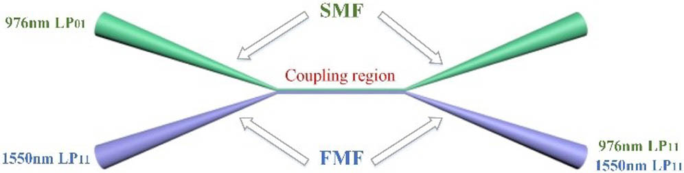
First, in order to achieve simultaneous mode conversion from 976 nm mode to 976 nm HOM and also mode multiplexing at two different wavelengths, a WDM-MSC is designed and fabricated, made up of a single-mode fiber (Nufern, 1060-XP) and a two-mode fiber (OFS, step-index)[27]. The schematic structure of the WDM-MSC is shown in Fig. 1. The weak fusion technique[28] is adopted in our manufacturing process for the sake of keeping the cylindrical symmetry of the fused fibers. The intensity distribution of the converted 976 nm mode is given in Fig. 2(a), showing a high purity of >90%. Foran input 976 nm light of 100 mW, the output power at the FMF terminal is about 89 mW, which gives a converting and coupling efficiency of 89%, with an insertion loss of 0.9 dB. For 1550 nm input light into the FMF input port, the output power at the FMF terminal has an insertion loss of 1.2 dB. More efforts to optimize the WDM-MSC fabrication may bring about better performance, including increasing coupling efficiency and reducing insertion loss.

Figure 1.Structure of the WDM-MSC.
Figure 2.(a) Converted mode, (b) mode at the FM-EDF input port, and (c) mode at the FM-EDF output port.
The amplified spontaneous emission (ASE) spectra when the FM-EDF is pumped by the mode of the 976 nm laser with different powers are given in Fig. 3, showing that the ASE peak of the FM-EDF is still around 1530 nm. The ASE spectrum becomes saturated when the pump power is increased to 200 mW due to the saturation of the population inversion. A light of 1550 nm mode is injected into the WDM-MSC FMF input port, and the output spectra after the amplification by the FM-EDF amplifier are measured by the optical spectrum analyzer (OSA). Figure 4(a) shows the spectral evolution when the pump power is increased. The central wavelength remains unchanged. What is more, we compared the amplified spectra at different wavelengths, where the pump power and the input signal power are kept the same, as the results show in Fig. 4(b). It is seen that the FM-EDF amplifier has a comparable gain bandwidth with the single-mode EDF amplifier.
Figure 3.ASE spectra under different pump powers.
Figure 4.Amplified spectra of the FM-EDF amplifier (a) with different pump powers of mode and (b) at different signal wavelengths.
The experimental setup of our all-FMF ring lasers is shown in Fig. 5. The converted 976 nm pump light is injected into a length of 1 m FM-EDF (19/125 μm, ) through our homemade WDM-MSC. An FMF isolator is used to eliminate the influence from backscattering light and ensure unidirectional operation. An FMF coupler, composed of two identical two-mode fibers with a power splitting ratio of 95:5, is fabricated using the light source of 1550 nm mode, aiming to extract the HOM light power out of the ring cavity. The CNT film placed between two FMF connectors is characterized as the saturable absorber for mode-locked pulse generation. All the components in the laser cavity are connected using FMF (OFS, two-mode step index fiber, 19/125 μm). The total length of the cavity is about 6.5 m. The output spectrum is measured by the OSA (YOKOGAWA, AQ6370 C) and the pulse trains are recorded by an oscilloscope (SDA 6000 A). The output beam profiles are recorded using a CCD camera (CinCam IR).
Figure 5.Schematic setup of our proposed all-FMF ring laser. FM-EDF: few-mode erbium-doped fiber; ISO: isolator; CNT-SA: carbon nanotube saturable absorber; OSA: optical spectrum analyzer; OSC: oscilloscope; CCD: charge coupled device; Col: collimator; PC: polarization controller.
The threshold power of our all-FMF ring laser is about 200 mW and it can be easily mode locked when the pump power is increased above its threshold. We used an oscilloscope and an OSA to characterize the pulse train and the output spectrum with the pump power fixed at 340 mW, as shown in Figs. 6(a) and 6(b). The pulse has a duration of 34 ns with a repetition rate of 30.58 MHz, and the center wavelength of the all-FMF ring laser is about 1559.64 nm. The 3 dB spectral bandwidth is relatively small, which is measured at about 0.33 nm under the pump power of 340 mW. The insert in Fig. 6(b) shows the measured spectrum from 1558 nm to 1562 nm.
Figure 6.Output mode-locked (a) pulse trains, (b) spectrum at a pump power of 340 mW.
In order to confirm the mode-locking operation, we measured the output spectra at different pump powers, as shown in Fig. 7(a). The 3 dB bandwidth of the spectrum suddenly narrows when decreasing the pump power to the threshold, measured to be about 0.04 nm, and the mode-locking state becomes unstable once the pump power exceeds 340 mW. But it can resume mode-locking operation again once we decrease the pump power. Figure 7(b) shows the evolution of the average output power and 3 dB bandwidth when the pump power increases from 180 mW to 340 mW. It is noted that, due to the fabrication technology limitation in the laboratory, the total loss of our homemade WDM-MSC and FMF-FMF coupler cannot be small enough. It may be responsible for the relatively low average output power. A lot of effort needs to be made to reduce the total loss and increase the average output power.
Figure 7.(a) Mode-locked optical spectrum evolution with different pump powers; (b) average output power and 3 dB bandwidth versus pump power.
Figure 8(a) shows the radio-frequency (RF) spectrum measured with a span of 1 GHz and a resolution bandwidth of 200 Hz. Figure 8(b) shows the fundamental peak located at the cavity repetition rate of 30.58 MHz with a resolution of 1 Hz. It exhibits a signal-to-noise ratio of 71.27 dB, which indicates that the all-FMF ring laser operates at a stable mode-locking state.
Figure 8.(a) RF spectrum of the all-FMF laser with a span of 1 GHz, (b) the fundamental peak located at the cavity repetition rate of 30.58 MHz with a resolution bandwidth of 1 Hz.
Since the FMF-FMF coupler is made using the light of 1550 nm high order mode, it can directly extract the mode out of the all-FMF ring cavity. On this basis, the generation of two cylindrical vector beams can be routinely realized by separating the degenerate mode. is injected into the cavity to change the fiber structure and refine the output polarization state to generate high purity or modes, which are CVBs. By adjusting the placed at the FMF output, two spatial distributions that have annular intensity profiles with a dark spot at the center are achieved. One is mode, also called the azimuthally polarized beam (APB). Another is mode, called the radially polarized beam (RPB). After placing a linear polarizer after the collimator, the doughnut-shaped fields are filtered into two parts and rotate with the linear polarizer, which can represent the typical characteristics of CVBs. Figures 9(a) and 9(b) show the intensity distributions of two CVBs recorded by our CCD camera (CinCam IR). The purity of these two polarized beams is also measured according to a Bezier curve with peak value representing the HOM component and valley value representing the fundamental mode component, to be about 96.7% and 95.2%, respectively. Figs. 9(a1)–9(a4) show the intensity distributions of the RPB after passing through a polarizer. Figures 9(b1)–9(b4) show the intensity distributions of the APB after passing through a polarizer.
Figure 9.Intensity distributions of (a) APB and (b) RPB without a polarizer before and after passing a linear polarizer.
In summary, we have demonstrated an all-FMF ring laser generating a mode-locked pulse with high purity CVB emission. The mode-locked pulse has a spectrum bandwidth of 0.33 nm with a repetition rate of 30.58 MHz and a signal-to-noise ratio of 71.27 dB. The APB and the RPB with purities measured to be 96.7% and 95.2%, respectively, have also been obtained. To the best of our knowledge, this is the first report on generating a mode-locked pulse from an all-FMF ring laser. Our future work will focus on reducing the total loss of the laser cavity and increasing the average output power. This simple and novel all-FMF laser source may find great applications in MDM systems to enhance the optical fiber communication capacity.
References
[1] H. Chen, C. Jin, B. Huang, N. Fontaine, R. Ryf, K. Shang, N. Gregoire, S. Morency, R. J. Essiambre, G. Li, Y. Messaddeq, S. LaRochelle. Nat. Photonics, 10, 529(2016).
[2] J. V. Weerdenburg, R. Ryf, J. C. Alvarado-Zacarias, R. A. Alvarez-Aguirre, N. K. Fontaine, H. Chen, R. A. Correa, Y. Sun, L. G. Nielsen, R. V. Jensen, R. Lingle, T. Koonen, C. Okonkwo. J. Lightwave Technol., 36, 1369(2018).
[3] D. J. Richardson, J. M. Fini, L. E. Nelson. Nat. Photonics., 7, 354(2013).
[4] E. Nazemosadat, A. Mafi. Opt. Express, 21, 30739(2013).
[5] Z. Feng, H. Ji, M. Tang, L. Yi, L. Gan, L. Xue, Q. Wu, B. Li, J. Zhao, W. Tong, S. Fu, D. Liu, W. Hu. Chin. Opt. Lett., 15, 080602(2017).
[6] F. Poletti, P. Horak. J. Opt. Soc. Am. B, 25, 1645(2008).
[7] H. Pourbeyram, G. P. Agrawal, A. Mafi. Appl. Phys. Lett., 102, 201107(2013).
[8] P. W. Smith. Appl. Phys. Lett., 13, 235(1968).
[9] J. Demas, P. Steinvurzel, B. Tai, L. Rishoj, Y. Chen, S. Ramachandran. Optica, 2, 14(2015).
[10] L. G. Wright, W. H. Renninger, D. N. Christodoulides, F. W. Wise. Opt. Express, 23, 3492(2015).
[11] Z. Liu, L. G. Wright, D. N. Christodoulides, F. W. Wise. Opt. Lett., 41, 3675(2016).
[12] T. Hellwig, T. Walbaum, C. Fallnich. Appl. Phys. B, 112, 499(2013).
[13] T. Wang, A. Yang, F. Shi, Y. Huang, J. Wen, X. Zeng. Photon. Res., 7, 42(2019).
[14] Q. Zhan. Adv. Opt. Photon., 1, 1(2009).
[15] B. Sun, A. Wang, L. Xu, C. Gu, Z. Lin, H. Ming, Q. Zhan. Opt. Lett., 37, 464(2012).
[16] H. Wan, H. Li, C. Wang, B. Sun, Z. Zhang, W. Wei, L. Zhang. IEEE Photonics J., 9, 7100608(2017).
[17] F. Wang, F. Shi, T. Wang. IEEE Photonics Technol. Lett., 29, 747(2017).
[18] H. Wan, J. Wang, L. Zhang. Opt. Express, 25, 11444(2017).
[19] Y. Cai, J. Wang, J. Zhang, H. Wan, Z. Zhang, L. Zhang. Chin. Opt. Lett., 16, 010602(2018).
[20] T. Wang, F. Wang, F. Shi, F. Pang, S. Huang, T. Wang, X. Zeng. J. Lightwave Technol., 35, 2161(2017).
[21] W. Zhang, L. Huang, K. Wei, P. Li, B. Jiang, D. Mao, F. Gao, T. Mei, G. Zhang, J. Zhao. Opt. Lett., 41, 5082(2016).
[22] Z. Zhang, W. Wei, L. Tang, J. Yang, J. Guo, L. Ding, Y. Li. Chin. Opt. Lett., 16, 102401(2018).
[23] L. G. Wright, D. N. Christodoulides, F. W. Wise. Science, 358, 94(2017).
[24] Y. Wang, Y. Tang, S. Yan, J. Xu. Laser Phys. Lett., 15, 085101(2018).
[25] H. Qin, X. Xiao, P. Wang, C. Yang. Opt. Lett., 43, 1982(2018).
[26] Y. Ding, X. Xiao, P. Wang, C. Yang. Opt. Express, 27, 11435(2019).
[27] T. Wang, F. Shi, Y. Huang, J. Wen, Z. Luo, F. Pang, T. Wang, X. Zeng. Opt. Express, 26, 11850(2018).
[28] R. Ismaeel, T. Lee, B. Oduro, Y. Jung, G. Brambilla. Opt. Express, 22, 11610(2014).