• Chinese Journal of Lasers
  • Vol. 50, Issue 17, 1714012 (2023)
Jiahua Cai1, Baolong Zhang2, Chunyan Geng1, Sibo Hao3, Sai Chen1、4, and Xiaojun Wu1、4、*
Author Affiliations
  • 1School of Electronic and Information Engineering, Beihang University, Beijing 100191, China
  • 2Beijing National Laboratory for Condensed Matter Physics, Institute of Physics, Chinese Academy of Sciences, Beijing 100190, China
  • 3School of Cyber Science and Technology, Beihang University, Beijing 100191, China
  • 4Beijing Key Laboratory for Microwave Sensing and Security Applications, Beihang University, Beijing 100191, China
  • show less
    DOI: 10.3788/CJL230435 Cite this Article Set citation alerts
    Jiahua Cai, Baolong Zhang, Chunyan Geng, Sibo Hao, Sai Chen, Xiaojun Wu. Lithium Niobate Strong‑Field Terahertz Nonlinear Time‑Domain Spectroscopy System[J]. Chinese Journal of Lasers, 2023, 50(17): 1714012 Copy Citation Text show less
    Strong field THz nonlinear time domain spectrometer based on lithium niobate pumped by a femtosecond laser amplifier
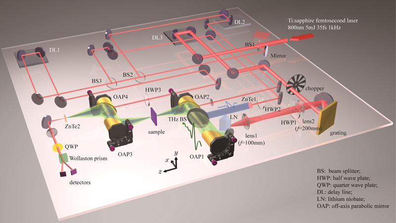
    Fig. 1. Strong field THz nonlinear time domain spectrometer based on lithium niobate pumped by a femtosecond laser amplifier
    Nonlinear strong field THz path and characterization of the realized strong THz pulse. (a) Optical path setup for the strong THz spectroscopy (it is necessary to replace the 50∶50 beam splitter in Fig. 1 with a mirror to concentrate the power of the pump light input to lithium niobate); (b) measured THz energy and corresponding conversion efficiency as a function of the pump power; (c) focused THz beam profile with a diameter of about 1.6 mm (1/e) measured at the focus of OAP2; (d)(e) a typical strong THz temporal waveform when the pump power is 1.5 W and its corresponding frequency spectrum with a peak frequency of 0.4 THz; (f) detection of focused THz beam profile using liquid crystal thermochromic paper
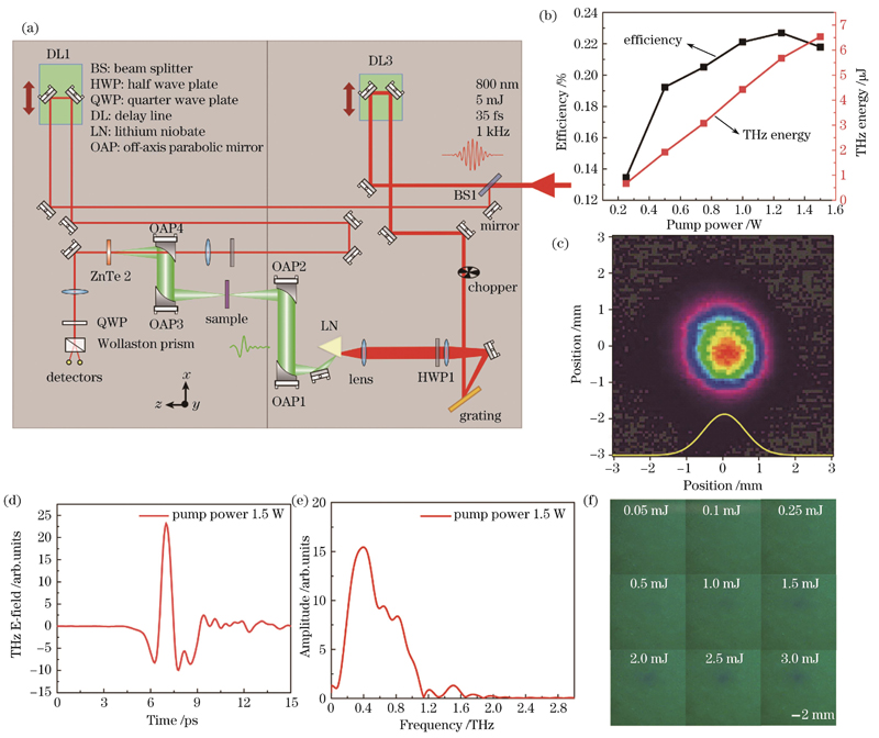
    Fig. 2. Nonlinear strong field THz path and characterization of the realized strong THz pulse. (a) Optical path setup for the strong THz spectroscopy (it is necessary to replace the 50∶50 beam splitter in Fig. 1 with a mirror to concentrate the power of the pump light input to lithium niobate); (b) measured THz energy and corresponding conversion efficiency as a function of the pump power; (c) focused THz beam profile with a diameter of about 1.6 mm (1/e) measured at the focus of OAP2; (d)(e) a typical strong THz temporal waveform when the pump power is 1.5 W and its corresponding frequency spectrum with a peak frequency of 0.4 THz; (f) detection of focused THz beam profile using liquid crystal thermochromic paper
    Relative THz transmittance of the doped and high-resistivity Si as a function of Z-position
    Fig. 3. Relative THz transmittance of the doped and high-resistivity Si as a function of Z-position
    Strong field THz induced nonlinear frequency modulation. (a) Schematic of TM polarization of the incident THz pulse; (b)(c) measured transmission spectra under TM polarization at the incident field intensities of 2.5 and 180 kV/cm and its corresponding simulation results
    Fig. 4. Strong field THz induced nonlinear frequency modulation. (a) Schematic of TM polarization of the incident THz pulse; (b)(c) measured transmission spectra under TM polarization at the incident field intensities of 2.5 and 180 kV/cm and its corresponding simulation results
    THz pump-THz probe (TPTP) technology. (a) Optical path diagram of TPTP system; (b) relation between the polarization direction of THz pump and THz probe and the orientation of SRRs; (c) typical THz probe transmission spectra before and after THz pump, showing a frequency shift of 45 GHz; (d) TPTP dynamic curve of resonant frequency-time delay for THz-nano metasurface on highly resistive silicon substrate
    Fig. 5. THz pump-THz probe (TPTP) technology. (a) Optical path diagram of TPTP system; (b) relation between the polarization direction of THz pump and THz probe and the orientation of SRRs; (c) typical THz probe transmission spectra before and after THz pump, showing a frequency shift of 45 GHz; (d) TPTP dynamic curve of resonant frequency-time delay for THz-nano metasurface on highly resistive silicon substrate
    Optical pump-strong and weak THz alternate probe technology. (a) Optical path diagram of optical pump- strong and weak THz alternate probe system; (b)(c) THz transmission spectra with different incident field strengths; (d) numerical simulation results corresponding to (b) and (c)
    Fig. 6. Optical pump-strong and weak THz alternate probe technology. (a) Optical path diagram of optical pump- strong and weak THz alternate probe system; (b)(c) THz transmission spectra with different incident field strengths; (d) numerical simulation results corresponding to (b) and (c)
    Optical pump-THz probe (OPTP) technology. (a) Optical path of OPTP system; (b)(c) weak-field THz probe temporal pulse waveform generated by ZnTe crystal optical rectification and its frequency spectrum; (d) THz time-resolved spectrum of N-doped silicon probed by weak-field THz under pump excitation with central wavelength of 800 nm and pumping fluence of 63 μJ/mm2; (e) under the same pump conditions, time-resolved spectrum of 15 nm thick topological insulator Bi2Te3 film grown on a single-sided polished sapphire substrate was detected by the strong-field THz probe
    Fig. 7. Optical pump-THz probe (OPTP) technology. (a) Optical path of OPTP system; (b)(c) weak-field THz probe temporal pulse waveform generated by ZnTe crystal optical rectification and its frequency spectrum; (d) THz time-resolved spectrum of N-doped silicon probed by weak-field THz under pump excitation with central wavelength of 800 nm and pumping fluence of 63 μJ/mm2; (e) under the same pump conditions, time-resolved spectrum of 15 nm thick topological insulator Bi2Te3 film grown on a single-sided polished sapphire substrate was detected by the strong-field THz probe
    THz emission spectroscopy technology. (a) Optical path of THz emission spectroscopy system; (b) femtosecond laser pulse exciting W/CoFeB/Pt heterostructures to generate THz radiation; (c)(d) principle and waveform of the radiated THz signal variation induced by external opposite magnetic fields
    Fig. 8. THz emission spectroscopy technology. (a) Optical path of THz emission spectroscopy system; (b) femtosecond laser pulse exciting W/CoFeB/Pt heterostructures to generate THz radiation; (c)(d) principle and waveform of the radiated THz signal variation induced by external opposite magnetic fields
    Jiahua Cai, Baolong Zhang, Chunyan Geng, Sibo Hao, Sai Chen, Xiaojun Wu. Lithium Niobate Strong‑Field Terahertz Nonlinear Time‑Domain Spectroscopy System[J]. Chinese Journal of Lasers, 2023, 50(17): 1714012
    Download Citation