• Photonics Research
  • Vol. 7, Issue 11, 1296 (2019)
Lei Kang1、2、†,*, Huaguang Bao1、†, and Douglas H. Werner1、3、*
Author Affiliations
  • 1Department of Electrical Engineering and Center for Nanoscale Science, The Pennsylvania State University, University Park, Pennsylvania 16802, USA
  • 2e-mail: lzk12@psu.edu
  • 3e-mail: dhw@psu.edu
  • show less
    DOI: 10.1364/PRJ.7.001296 Cite this Article Set citation alerts
    Lei Kang, Huaguang Bao, Douglas H. Werner. Interference-enhanced optical magnetism in surface high-index resonators: a pathway toward high-performance ultracompact linear and nonlinear meta-optics[J]. Photonics Research, 2019, 7(11): 1296 Copy Citation Text show less
    Meta-optics based on Si resonators on a plasmonic substrate. (a) Illustration of a unit cell of the metasurface consisting of an array of a-Si:H nanodisks on top of an optically thick Au ground plane. Geometrical parameters: P=720 nm, D=450 nm, and h=385 nm. (b) Schematic of the proposed meta-optical systems with finite array size, in which square arrays having m×ma-Si:H nanodisk elements are located on top of an infinite Au substrate. (c) Calculated magnetic field (|H|) obtained from a magnetic probe located at the center of the central resonator for a series of array sizes used in numerical simulations. The gray dashed line is used to guide the eye. (d) Q-factor and the maximum enhancement factor |H|max as functions of the array size. The corresponding values in the periodic case are illustrated as well. (e)–(h) Calculated magnetic field and electric field vector distribution in the y–z plane, in the case of m=1, 9, and 15 as well as the periodic structure at the peak frequency identified in (c).
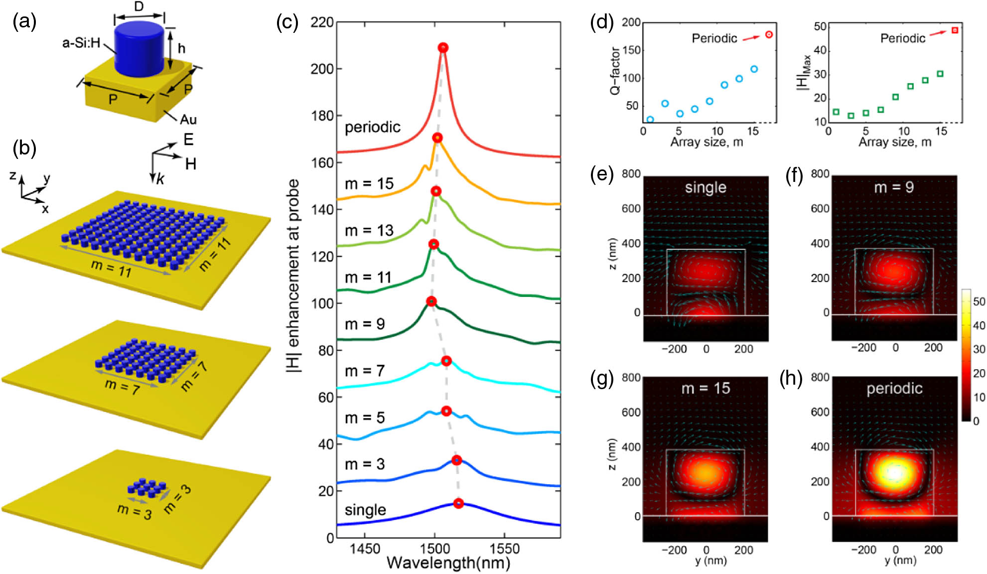
    Fig. 1. Meta-optics based on Si resonators on a plasmonic substrate. (a) Illustration of a unit cell of the metasurface consisting of an array of a-Si:H nanodisks on top of an optically thick Au ground plane. Geometrical parameters: P=720  nm, D=450  nm, and h=385  nm. (b) Schematic of the proposed meta-optical systems with finite array size, in which square arrays having m×ma-Si:H nanodisk elements are located on top of an infinite Au substrate. (c) Calculated magnetic field (|H|) obtained from a magnetic probe located at the center of the central resonator for a series of array sizes used in numerical simulations. The gray dashed line is used to guide the eye. (d) Q-factor and the maximum enhancement factor |H|max as functions of the array size. The corresponding values in the periodic case are illustrated as well. (e)–(h) Calculated magnetic field and electric field vector distribution in the yz plane, in the case of m=1, 9, and 15 as well as the periodic structure at the peak frequency identified in (c).
    All-optical ultrafast modulation enabled by critical coupling with the guided resonance of meta-optical systems. (a) Schematic of the unit cell used in numerical simulations. The geometrical parameters are the same as those used in Fig. 1(a). The ultrafast nonlinear responses of the proposed metasurface are obtained by implementing the theoretical model presented in Ref. [38]. (b) Transient absolute reflectance modulation (ΔR) under pumping at an 800 nm wavelength with a pump fluence of 0.1 mJ/cm2. The pump intensity is 10% of that used in Ref. [38]. For clarity, the results around the resonance are enlarged and shown on the right (dashed-green box). The simulated static reflectance and absorption spectra are shown in the inset. (c) Relative differential reflectance (ΔR/R) at a few wavelengths of interest near the resonance.
    Fig. 2. All-optical ultrafast modulation enabled by critical coupling with the guided resonance of meta-optical systems. (a) Schematic of the unit cell used in numerical simulations. The geometrical parameters are the same as those used in Fig. 1(a). The ultrafast nonlinear responses of the proposed metasurface are obtained by implementing the theoretical model presented in Ref. [38]. (b) Transient absolute reflectance modulation (ΔR) under pumping at an 800 nm wavelength with a pump fluence of 0.1  mJ/cm2. The pump intensity is 10% of that used in Ref. [38]. For clarity, the results around the resonance are enlarged and shown on the right (dashed-green box). The simulated static reflectance and absorption spectra are shown in the inset. (c) Relative differential reflectance (ΔR/R) at a few wavelengths of interest near the resonance.
    Polarization sensitive ultrafast modulation based on Si nanodisks with an elliptical cross-section. (a) Schematic of the unit cell used in numerical simulations. The major and minor axes of the elliptical cross-section are 500 and 450 nm, respectively. (b) The cross- and co-polarization reflectance spectra when the metasurface is illuminated by a y-polarized wave. Inset indicates the orientation of the Si nanodisk in the x–y plane. Calculated magnetic field (normalized to that of the incident wave) and its vector distribution in a plane cut across the middle of the resonator at the two resonance wavelengths (bottom). Transient absolute reflectance modulation for (c) the co-polarization reflected wave (ΔRyy) and (f) the cross-polarization reflected wave (ΔRxy) under pumping at an 800 nm wavelength with a pump fluence of 0.1 mJ/cm2. Relative differential reflectance (d), (e) (ΔRyy/Ryy) and (g) (ΔRxy/Rxy) at a few wavelengths of interest.
    Fig. 3. Polarization sensitive ultrafast modulation based on Si nanodisks with an elliptical cross-section. (a) Schematic of the unit cell used in numerical simulations. The major and minor axes of the elliptical cross-section are 500 and 450 nm, respectively. (b) The cross- and co-polarization reflectance spectra when the metasurface is illuminated by a y-polarized wave. Inset indicates the orientation of the Si nanodisk in the xy plane. Calculated magnetic field (normalized to that of the incident wave) and its vector distribution in a plane cut across the middle of the resonator at the two resonance wavelengths (bottom). Transient absolute reflectance modulation for (c) the co-polarization reflected wave (ΔRyy) and (f) the cross-polarization reflected wave (ΔRxy) under pumping at an 800 nm wavelength with a pump fluence of 0.1  mJ/cm2. Relative differential reflectance (d), (e) (ΔRyy/Ryy) and (g) (ΔRxy/Rxy) at a few wavelengths of interest.
    Exploiting the magnetic response in individual high-index resonators for excitation of SPPs. (a) Schematic of the meta-optical system that includes a Si cuboid located on a gold substrate. Around the magnetic Mie resonance of the resonator, SPPs primarily propagating along the +y and −y directions will be excited on the surface of the gold substrate. A y-polarized plane wave normally illuminates the resonator from the top. A magnetic (H) field probe is placed in the center of the cuboid, and an electric field probe is placed 10 nm above the gold surface at y=5 μm. (b) Magnitude of Ez detected at the E-field probe and (c) magnitude and (d) phase of Hx detected at the H-field probe, when the SP wave is excited by a Si cuboid of two distinct geometries (Cuboid A: l=400 nm, w=200 nm; Cuboid B: l=480 nm, w=240 nm). For comparison purposes, the results based on a glass cuboid of the same dimensions are shown in (b)–(d) as well (dashed curves). (e), (f) The magnetic field distribution for both excitation systems at a wavelength where |Ez| peaks. The electric field distribution of SPPs excited on the gold surface (g) by Cuboid A and (h) by Cuboid B.
    Fig. 4. Exploiting the magnetic response in individual high-index resonators for excitation of SPPs. (a) Schematic of the meta-optical system that includes a Si cuboid located on a gold substrate. Around the magnetic Mie resonance of the resonator, SPPs primarily propagating along the +y and y directions will be excited on the surface of the gold substrate. A y-polarized plane wave normally illuminates the resonator from the top. A magnetic (H) field probe is placed in the center of the cuboid, and an electric field probe is placed 10 nm above the gold surface at y=5  μm. (b) Magnitude of Ez detected at the E-field probe and (c) magnitude and (d) phase of Hx detected at the H-field probe, when the SP wave is excited by a Si cuboid of two distinct geometries (Cuboid A: l=400  nm, w=200  nm; Cuboid B: l=480  nm, w=240  nm). For comparison purposes, the results based on a glass cuboid of the same dimensions are shown in (b)–(d) as well (dashed curves). (e), (f) The magnetic field distribution for both excitation systems at a wavelength where |Ez| peaks. The electric field distribution of SPPs excited on the gold surface (g) by Cuboid A and (h) by Cuboid B.
    Directional excitation of SPPs using a pair of high-index resonators. (a) Schematic of the meta-optical system for directional generation of SPPs. A y-polarized plane wave normally illuminates the resonators from the top. To monitor the excited SP waves, two electric field probes are placed 10 nm above the gold surface at y=−5 and +5 μm, respectively. (b) |Ez| detected at the two E-field probes and, (c) the corresponding ratio between |Ez| at the two probes (|Ez|probe1/|Ez|probe2), when the two cuboids are separated by a series of distances (Dis). (d) |Ez|2 distribution on an imaginary circle (with a radius of 10 μm) at a wavelength of 1636 nm when Dis=450 nm and (e) the corresponding electric field distribution of SPPs excited on the gold surface. (f)–(h) |Ez|2 distributions corresponding to the |Ez| ratio peaks in (c) on the imaginary circle.
    Fig. 5. Directional excitation of SPPs using a pair of high-index resonators. (a) Schematic of the meta-optical system for directional generation of SPPs. A y-polarized plane wave normally illuminates the resonators from the top. To monitor the excited SP waves, two electric field probes are placed 10 nm above the gold surface at y=5 and +5  μm, respectively. (b) |Ez| detected at the two E-field probes and, (c) the corresponding ratio between |Ez| at the two probes (|Ez|probe1/|Ez|probe2), when the two cuboids are separated by a series of distances (Dis). (d) |Ez|2 distribution on an imaginary circle (with a radius of 10 μm) at a wavelength of 1636 nm when Dis=450  nm and (e) the corresponding electric field distribution of SPPs excited on the gold surface. (f)–(h) |Ez|2 distributions corresponding to the |Ez| ratio peaks in (c) on the imaginary circle.
    Lei Kang, Huaguang Bao, Douglas H. Werner. Interference-enhanced optical magnetism in surface high-index resonators: a pathway toward high-performance ultracompact linear and nonlinear meta-optics[J]. Photonics Research, 2019, 7(11): 1296
    Download Citation