
Mei-Yuan Gu, Jing-Biao Liu, Guang-Yi Wang, Yan Liang, Fu-Peng Li. Memcapacitor-based multivibrator and its experiments [J]. Acta Physica Sinica, 2019, 68(22): 228401-1
- Acta Physica Sinica
- Vol. 68, Issue 22, 228401-1 (2019)
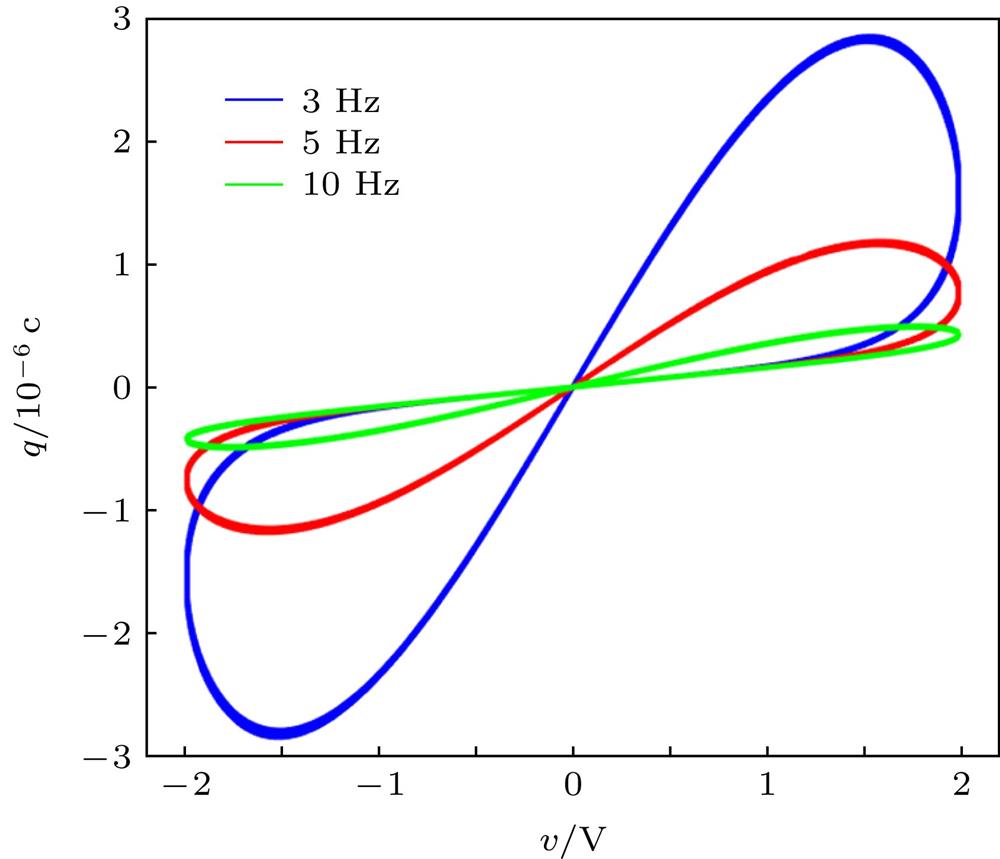
Fig. 1. q -v pinched hysteresis loops of memcapacitor
忆容器的q -v 特性曲线
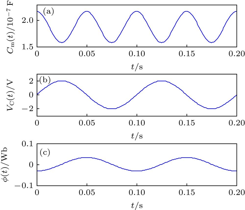
Fig. 2. Time domain waveforms of C m, v C and flux under periodic excitation signal: (a)
; (b)
; (c)
.
正弦交流电激励下忆容器
、
和
的时域波形(a)
; (b)
; (c)
Fig. 3. Dynamic path map of memcapacitor (
): (a)Dynamic path map ; (b) Memcapacitor circuit and Vs waveform.
忆容器的动态路径图(
) (a)动态路径图; (b)忆容器电路和Vs波形
Fig. 4. A voltage-controlled memcapacitor emulator压控型忆容器仿真器
Fig. 5. q- v pinched hysteresis loops of the memcapacitor simulator: the abscissa and ordinate correspond to
and
, respectively: (a) Results of circuit simulation.The display range of ordinates is [–10, 10] V, and the display range of abscissa is [–5, 5] V; (b) result of hardware experiment circuit; the abscissa and ordinates are shown as 1 V/lattice and 2 V/lattice, respectively.
忆容器仿真器的
曲线(横坐标和纵坐标分别对应于
和
) (a)仿真电路的测试结果图, 纵坐标显示范围[–10, 10] V, 横坐标显示范围[–5, 5] V; (b)硬件实验电路的测试结果, 横坐标和纵坐标显示分别为1 V/格和2 V/格
Fig. 6. Multivibrator based on memcapacitor.基于忆容器的多谐振荡器
Fig. 7. In R 10C m circuit, the time-domain waveforms of flux and voltage of the memcapacitor and voltage vR : (a)
; (b) v C; (c) v O; (d) v R.
回路中忆容器的磁通、电压和
的时域波形 (a)
; (b) v C; (c) v O; (d) v R
Fig. 8. Simulation waveforms of memcapacitor multivibrator: The display range of vertical coordinates
、
and
are all
, but the display range of vertical coordinates of
is
.
忆容器多谐振荡器仿真电路波形(
、
和
纵坐标的显示范围均为
,
纵坐标的显示范围是
)
Fig. 9. Measurement of oscillating waveforms in hardware circuit: (The vertical axes of
,
and
are both 2 V/lattice, the vertical axes of
is 500 mV/lattice, The horizontal axes of all voltages are 100 ms/lattice).
硬件电路实测振荡波形(
、
和
幅值均为2 V/格,
为500 mV/格, 时间轴均为100 ms/格)
Fig. 10. Curve of Oscillator Performance Parameters with Circuit parameter changes (
as a parameter variable): (a) T ; (b) f ; (c) D .
作为参变量时, 振荡器性能参数随电路参数变化的曲线 (a) T ; (b) f ; (c) D
Fig. 11. Curve of oscillator performance parameters with circuit parameter changes (
as a parameter variable): (a) T ; (b) f ; (c) D .
作为参变量时, 振荡器性能参数随电路参数变化的曲线 (a) T ; (b) f ; (c) D
Fig. 12. Curve of Oscillator Performance Parameters with Circuit parameter changes (
as a parameter variable): (a) T ; (b) f ; (c) D .
作为参变量时, 振荡器性能参数随电路参数变化的曲线 (a) T ; (b) f ; (c) D
Fig. 13. Experimental oscillation waveforms of memcapacitor multivibrator: (a)
; (b)
. The vertical axes of
、
and
in Fig(a) and Fig (b) are both 2 V/lattice. The vertical and horizontal axes of
in Fig(a) are 100 mV/lattice and 50 ms/lattice, respectively. The vertical and horizontal axes of
in Fig(b) are 5 V/lattice and 100 ms/lattice, respectively.
忆容器振荡器硬件电路实验振荡波形(图(a)和(b)中
、
和
的纵轴均为2 V/格) (a)
, 其中
纵轴为100 mV/格, 时间轴为50 ms/格; (b)
, 其中
纵轴为5 V/格, 时间轴为100 ms/格
Fig. 14. Experimental oscillation waveforms of memcapacitor multivibrator: (a)
; (b)
. The vertical axis of
、
and
in Fig. (a) and Fig. (b) are both 2 V/lattice. The vertical and horizontal axes of
in Fig. (a) are 500 mV/lattice and 50 ms/lattice, respectively. The vertical and horizontal axes of
in Fig. (b) are 5 V/lattice and 100 ms/lattice, respectively.
忆容振荡器硬件电路实验振荡波形(图中
、
和
纵轴均为2 V/格, 图(a)中
纵轴为500 mV/格, 时间轴为50 ms/格, 图(b)中
纵轴为5 V/格, 时间轴为100 ms/格) (a)
; (b)
Fig. 15. Experimental oscillation waveforms of memcapacitor multivibrator: (a) C 2 = 146 nF; (b) C 2 = 256 nF. The vertical axes of
、
and
in Fig. (a) and Fig. (b) are both 2 V/lattice. The vertical and horizontal axes of
in Fig. (a) are 500 mV/lattice and 50 ms/lattice, respectively. The vertical and horizontal axes of
in Fig. (b) are 2 V/lattice and 100 ms/lattice, respectively.
忆容振荡器硬件电路实验振荡波形(图中
、
和
纵轴均为2 V/格, 图(a)中
纵轴为500 mV/格, 时间轴为50 ms/格, 图(b)中
纵轴为2 V/格, 时间轴为100 ms/格) (a) C 2 = 146 nF; (b) C 2 = 256 nF
Fig. 16. The pinched hysteresis loops of memcapacitor with different values of R 10 in oscillating circuit: (a)
; (b)
. The horizontal and vertical axes correspond to
and
, respectively.
为不同值时振荡电路中忆容器的滞回曲线(横坐标和纵坐标分别对应于
和
) (a)
; (b)

Set citation alerts for the article
Please enter your email address
© Copyright 2018-2021 | Chinese Laser Press. All Rights Reserved 沪ICP备15018463号-20