
Xiong Shen, Peng Wang, Jun Liu, Ruxin Li. Linear angular dispersion compensation of cleaned self-diffraction light with a single prism[J]. High Power Laser Science and Engineering, 2018, 6(2): 02000e23
- High Power Laser Science and Engineering
- Vol. 6, Issue 2, 02000e23 (2018)
Abstract
1 Introduction
Peta watt (PW) level laser systems, with focused laser peak intensity of about  or even higher, have been reported repeatedly[
 [
[
To build high temporal contrast laser systems, optical parametric chirped-pulse amplification (OPCPA)[
In theory, the temporal contrast of the first-order SD signal is the cube of the temporal contrast of the incident pulse as  , because the generated cleaned SD signals are spatially separated from the incident beams without use of any polarization discrimination devices. What is more, this technique can also achieve a high energy SD signal output using a cylinder mirror focusing on the incident beams, even with low energy-conversion efficiency[
Sign up for High Power Laser Science and Engineering TOC. Get the latest issue of High Power Laser Science and Engineering delivered right to you!Sign up now
In this study, we report the highest pulse energy and highest temporal contrast enhancement pulses generation based on the SD effect with two cylindrical convex lenses so far. More than  first-order SD signal with a temporal contrast of
  is generated with about five orders of magnitude improvement. The wings around the main pulse in
  ps are cleaned with a contrast improvement of about
  , which verifies the pulse cleaning ability of SD process. The cause of angular dispersion generation of the SD signals is also explored, and the linear angular dispersion is compensated with a single prism.
2 Principle and experimental setup
The SD process is a degenerated cascaded four-wave mixing (DCFWM) process[ , where
  is the time delay between the two input pulses[
 signal is the cube of that of the incident pulse
  . Furthermore, the generated signals and incident beams are separated spatially, which means no polarizer with a limited extinction ratio is needed, which is a main limitation for the XPW process. These properties indicate a potential high temporal contrast enhancement by using the SD process.
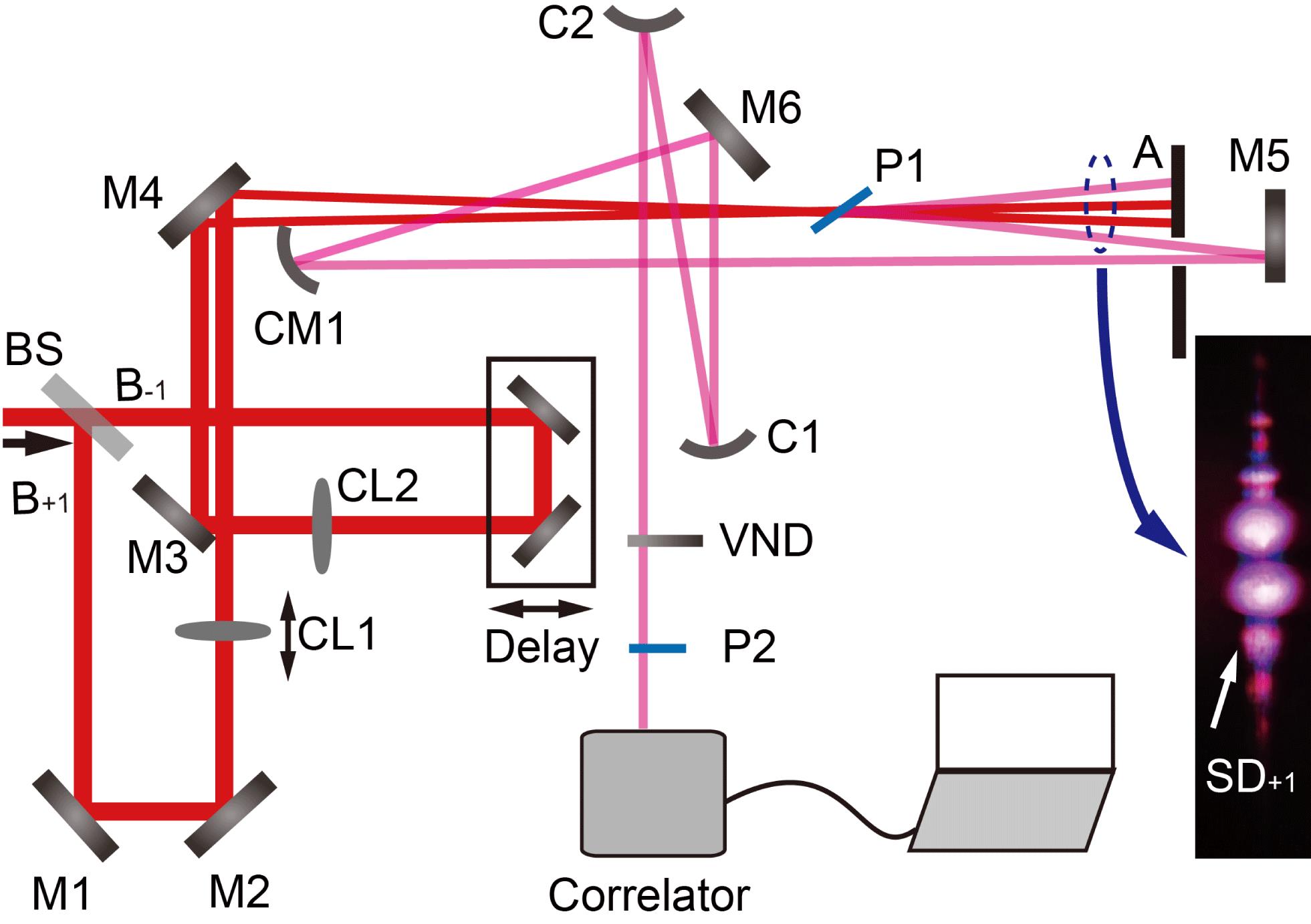
Figure  and
and  by a 50/50 beam splitter. Both
  and
and  are separately focused into a Kerr medium P1 by two plane-convex cylindrical lenses CL1 and CL2. There is a delay line in the path of
  . P1 is a 0.15 mm thick fused silica plate which is located about 60 mm behind the focus of the two lenses with a near Brewster angle to the two incident beams. The external crossing angle
  between the two incident beams is about
  , where the phase-matching condition can be easily satisfied[
 , then
  is collimated by a cylindrical reflective mirror CM1. The collimated
  beam is reduced in beam size to about 3 mm diameter by a spherical concave reflective mirror and a spherical convex reflective mirror, and is then taken to a commercial third-order cross-correlator (Amplitude Technologies Inc., Sequia 800) for temporal contrast measurement. A variable neutral-density (VND) filter is used to adjust the input energy into the correlator. P2 is inserted to create replicas of the main pulse of
  .
.
3 Results and discussion
3.1 High energy and high temporal contrast SD pulse generation
To generate SD signals with high energy and temporal contrast, experiments were performed with a commercial Ti:sapphire CPA laser system (Legend Elite Cryo PA, Coherent Inc.). The laser system produces 1 kHz/50 fs/800 nm/10 mJ pulses with a diameter of about 15 mm. The pulse energies of the two incident beams before the Kerr medium P1 are both about 4.9 mJ. The beam size on the Kerr medium is about  . About five diffracted orders of SD signals are generated beside each side of the two incident beams. The first-order SD signals
  and
and  are about
  and
and  , respectively. The energy-conversion efficiency from the two incident beams to
  is about 7.8%.
To characterize the temporal contrast of  , the diameter of signal
  beam is reduced to about 3 mm by C1 (spherical concave reflective mirror,
  ) and C2 (spherical convex reflective mirror,
  mm) first. Then, a 2 mm thick VND filter is used to adjust the input energy to the correlator to about 200 mW. A 1 mm thick fused silica plate is inserted in the path of
  to introduce reference post-pulses.
The measured temporal contrast curves of the input pulse and  are shown in Figure
  to
to  , and they are time symmetrical with replicas a’/b’/c’/d’/e’ after the main pulse, respectively. These replicas may come from reflection between front and rear surfaces of optical elements in the laser path. An amplified ASE-noise with contrast change from
  to
to  also exists around the main pulse. The 1 mm thick fused silica plate P2 introduces replicas A’ and C’ after the main pulse of
  with normalized intensity about
  and
and  , respectively, which are about one order lower than the values introduced by the front and rear sides reflection of a fused silica plate. It may be caused by the tilt of P2, that the replicas and the main pulse are not collinear entirely. Replicas A and B are time symmetrical with replicas A’ and B’. From the inset in Figure
  ps are cleaned with a contrast improvement of about
  , which verifies the pulse cleaning ability of SD process.
3.2 Analyzation of angular dispersion generation
The generation of the angular dispersion of  is caused by the different phase-matching condition of wavelength components of the two incident beams shown in Figure
For  , its phase-matching condition is
  . In the
  direction,
  denotes the wave vector of the longest wavelength component and
  the wave vector of the shortest wavelength component. Similarly, in the
  direction,
  denotes the wave vector of the longest wavelength component and
  the wave vector of the shortest wavelength component. Then the generated longest wavelength
  and shortest wavelength
  in
in  can be expressed as
  and
and  , respectively.
  is the original longest and
  the shortest wavelength of the incident pulses. The phase-matching conditions for the longest and shortest wavelength SD signals are
  and
and  , respectively. Then the dispersion angle
  of
of  is the angle between
  and
and  . It is related to the cross angle of the two incident beams, the shortest and the longest wavelength components of the two beams, and can be expressed as
  ,
,  ,
,  .
.
There is a little difference between the center wavelength of  and that of the incident pulses, and can be calculated according to the law of cosines:
  , where
  is the new generated center wavelength of
  and
and  the original center wavelength of the incident pulses. For
  nm,
nm,  . The new generated center wavelength of
  nm. It can be concluded that for a small crossing angle of the two incident beams, the generated first-order SD signals almost keep the same center wavelength of the incident pulses, and the SD process can be looked on as a frequency-conserving process.
3.3 Angular dispersion compensation
For an incident beam with a spectrum as shown in Figure  is about 28 nm with center wavelength at 803 nm. The generated dispersion angle
  mrad according to the equation of
  . Then the angular dispersion can be roughly calculated as
  mrad/nm. The divergence angle caused by the lenses CL1 and CL2 with 500 mm focal length is about
  mrad. After about 2000 mm, the beam width of the
  is about
  mm.
mm.
In the experiment, after propagation of about 2000 mm in air, the width of beam  is about 30 mm. We measured the spectra of
  at 30 different positions P0 to P29 in the horizontal direction, with every two positions separated by about 1 mm. Figure
  .
.  , the measured result of the angular dispersion of generated SD signal matches very well with the theoretically calculated result.
The scheme of angular dispersion compensation is shown in Figure  rad is used to compensate the angular dispersion in our experiment. In beam
  , longer wavelength is located far away from the two incident beams and shorter wavelength located closer to the two incident beams. A cylindrical reflective mirror with focal length of 200 mm located 400 mm behind the Kerr medium P1 is used to symmetrically focus
  .
.
For a prism with refractive index  and apex angle
  , we can obtain the angular dispersion of the prism[
 . According to the measurement, the angular dispersion of the generated
  is about 0.15 mrad/nm with center wavelength shifting from 795 nm to 815 nm. We just consider the two edge center wavelengths
  nm and
  nm here. We can calculate their refractive index according to Cauchy’s dispersion formula in the prism as
  and
and  , respectively.
The relation between  and
and  can be calculated with Snell’s law
  ,
,  and
and  rad. If the cross angle between the two output beams is about
  , the angle
  is the right output angle of the
  beam. The input angle of the
  beam can be calculated as about
  rad.
rad.
The angular dispersion compensated  propagates about 1500 mm, and is expanded to about 20 mm in the horizontal direction. The spectra of
  at five different positions with 5 mm apart are shown in Figure
As can be seen in Figure  at five different positions show a good coincidence. While, residual angular dispersion still exists, and it is clear that the compensation for the shorter wavelengths appears better than that for the longer wavelengths, we think this is the residual high-order angular dispersion as the center wavelengths vary nonlinearly relative to the five positions of equal interval.
4 Conclusion
In conclusion, temporal contrast enhancement by the SD process in a bulk Kerr medium possesses a few advantages compared to many other pulse cleaning techniques. The SD signals are spatially separated from the incident beams without the use of any polarization discrimination devices. It can also achieve a high energy SD signal output with a cylindrical mirror focusing on the incident beams even with low energy-conversion efficiency. The temporal contrast of the  signal is the cube of the temporal contrast of the incident pulse,
  in theory, which indicates a great potential of temporal contrast enhancement by the SD process.
In this study, a temporal contrast enhancement equipment based on SD effect with two cylindrical convex lenses is built. As high as  first-order SD signal at 800 nm with contrast of
  is generated with about five orders of magnitude improvement. Wings around the main pulse in
  are cleaned with a contrast improvement of about
  , which verifies the pulse cleaning ability of SD process. The cause of angular dispersion generation of the SD signals is also explored, and the angular dispersion is compensated with a single prism. It is expected to extend the SD process as an effective pulse cleaning method for high power laser at 1053 nm with a narrow spectral bandwidth and hundreds of femtosecond pulse duration.
References
[3] Z. Wang, C. Liu, Z. Shen, Q. Zhang, H. Teng, Z. Wei. Opt. Lett., 36, 3194(2011).
[4] T. J. Yu, S. K. Lee, J. H. Sung, J. W. Yoon, T. M. Jeong, J. Lee. Opt. Express, 20, 10807(2012).
[7] H. Kiriyama, M. Mori, A. S. Pirozhkov, K. Ogura, A. Sagisaka, A. Kon, T. Z. Esirkepov, Y. Hayashi, H. Kotaki, M. Kanasaki, H. Sakaki, Y. Fukuda, J. Koga, M. Nishiuchi, M. Kando, S. V. Bulanov, K. Kondo, P. R. Bolton, O. Slezak, D. Vojna, M. Sawicka-Chyla, V. Jambunathan, A. Lucianetti, T. Mocek. IEEE J. Sel. Top. Quantum Electron., 21, 18(2015).
[8] Y. I. Salamin, S. X. Hu, K. Z. Hatsagortsyan, C. H. Keitel. Phys. Rep., 427, 41(2006).
[9] P. B. Corkum, F. Brunel, N. K. Sherman, T. Srinivasanrao. Phys. Rev. Lett., 61, 2886(1988).
[13] M. P. Kalashnikov, E. Risse, H. Schonnagel, W. Sandner. Opt. Lett., 30, 923(2005).
[14] N. Xie, K. N. Zhou, W. Q. Huang, X. D. Wang, L. Sun, Y. Guo, Q. Li. Opt. Eng., 51, 5(2012).
[17] D. Homoelle, A. L. Gaeta, V. Yanovsky, G. Mourou. Opt. Lett., 27, 1646(2002).
[19] V. Chvykov, P. Rousseau, S. Reed, G. Kalinchenko, V. Yanovsky. Opt. Lett., 31, 1456(2006).
[21] F. J. Li, X. Shen, P. Wang, Y. Y. Li, J. Liu, Z. S. Wang, R. X. Li. Laser Phys. Lett., 13(2016).
[22] J. Liu, K. Okamura, Y. Kida, T. Kobayashi. Opt. Express, 18, 22245(2010).
[23] J. Liu, T. Kobayashi. Sensors, 10, 4296(2010).
[24] V. L. Vinetskii, N. V. Kukhtarev, S. G. Odulov, M. S. Soskin. Usp. Fiz. Nauk, 129, 113(1979).
[25] R. L. Fork, O. E. Martinez, J. P. Gordon. Opt. Lett., 9, 150(1984).

Set citation alerts for the article
Please enter your email address
© Copyright 2018-2021 | Chinese Laser Press. All Rights Reserved 沪ICP备15018463号-20