
Chong He, Cheng Zhou, Qian Zhou, Shiyi Xie, Mengzhe Xiao, Jiajun Tian, Yong Yao, "Simultaneous measurement of strain and temperature using Fabry–Pérot interferometry and antiresonant mechanism in a hollow-core fiber," Chin. Opt. Lett. 19, 041201 (2021)
- Chinese Optics Letters
- Vol. 19, Issue 4, 041201 (2021)
Abstract
1. Introduction
Fiber-optic strain sensors have demonstrated their potentials in structural health monitoring[
Antiresonance (AR) is generated through an AR reflecting fiber—a photonic bandgap waveguide with a core of low refractive index[
In this Letter, a dual-parameter fiber-optic sensor simultaneously measuring strain and temperature is proposed. The sensor works properly with the help of FP interference and AR mechanisms within the AR reflecting fiber constructed from single-mode fiber (SMF)–HCF–SMF. The specific structure comprises an axial FP cavity formed by the hollow core and a radial FP cavity by the cladding of an HCF, in which the FP interference and AR are generated. It is observed that the reflection spectra are composed of an FP-modulated AR envelope. Since the FP and AR mechanisms within the HCF are solely sensitive to strain and temperature, respectively, this configuration allows the proposed sensor to perform simultaneous measurement. To the best of our knowledge, this is the first time that a combination of FP interference and AR mechanism in an AR reflecting fiber has been applied to the simultaneous measurement of strain and temperature.
Sign up for Chinese Optics Letters TOC. Get the latest issue of Chinese Optics Letters delivered right to you!Sign up now
2. Sensor Structure and Working Principle
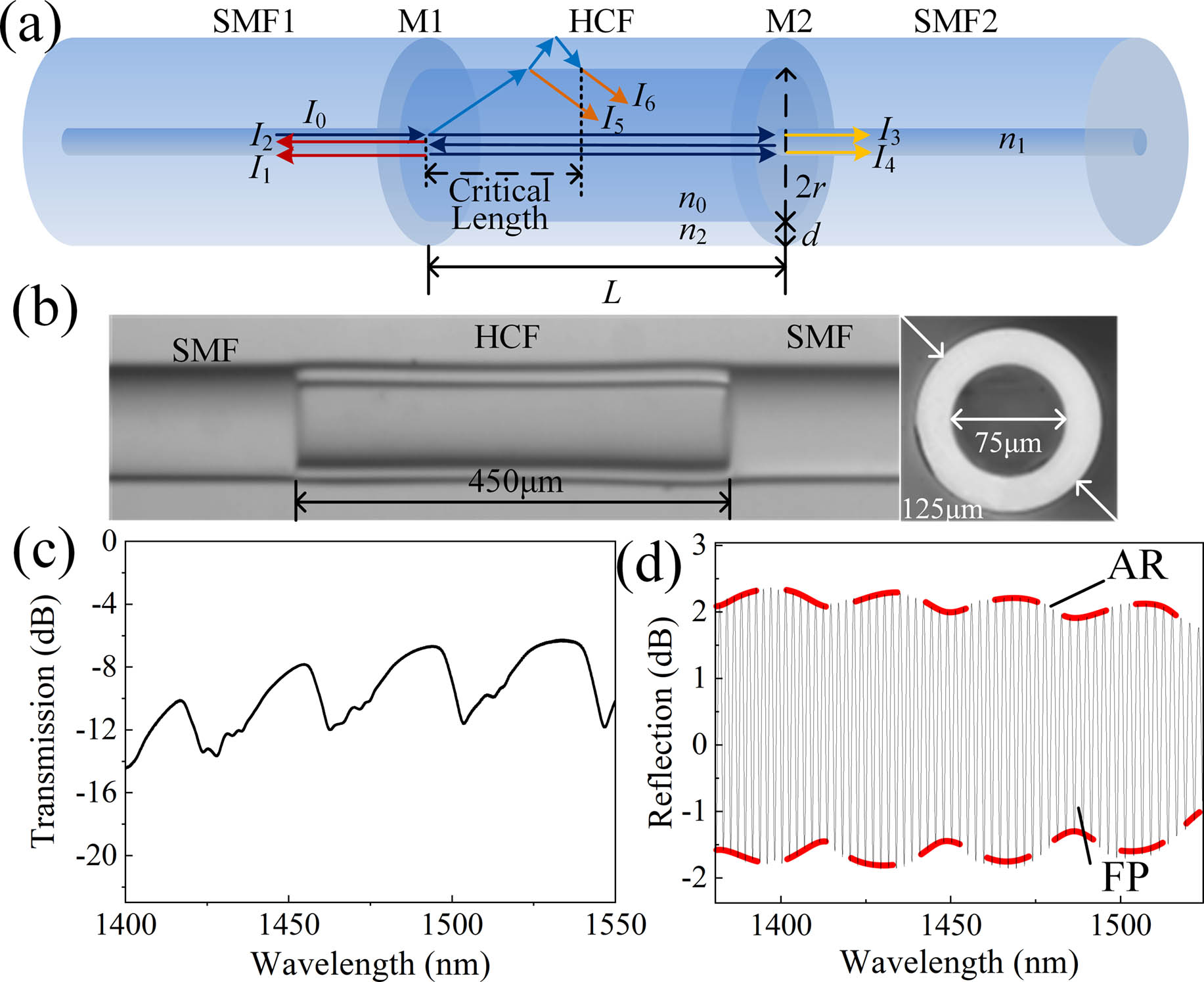
The proposed sensor was composed of an HCF, the cladding thickness and outer diameter of which were 25 µm and 125 µm, respectively. The HCF was sandwiched between two SMFs to form an AR reflecting fiber, as shown in Fig. 1(a). Several steps including fiber cleaving and splicing were required to prepare the proposed sensor. First, two SMFs were spliced onto each end of an HCF (TSP050150, Polymicro Technologies, USA), respectively, with a fiber splicer (FSM-80S, Fujikura, Japan). Second, the fabricated fiber segment was placed under a microscope, and an HCF of the desired length to form the cavity was cleaved. Finally, another SMF was spliced onto the HCF obtained from the second step. The fabricated sensor is exhibited in Fig. 1(b), together with the end face of the HCF used in the experiment.
![]()
Figure 1.(a) Schematic of the proposed sensor; (b) typical microscopic image of the fabricated sensor and the HCF cross section; (c) transmission spectrum of a sensor with an HCF of 2050 µm in length; (d) reflection spectrum of a sensor with an HCF of 450 µm in length.
Regarding the HCF part illustrated in Fig. 1(a), it has a length of
The AR mechanism in the SMF–HCF–SMF structure can be interpreted by the ARROW model[
A transmission spectrum of the proposed sensor with an HCF of 2050 µm in length is shown in Fig. 1(c). This shows that sharp dips occur at the resonant wavelengths of AR and indicates that FP interference is weak enough to be ignored in the forward propagation. The transmission energy of the AR mechanism will also be reflected by M2. However, AR mechanisms take effect and contribute to the reflection spectrum only if the HCF is longer than a certain length because AR is the result of the interference of two beams—the first reflected light at the air–silica interface,
Therefore, AR and FP interference both contribute to the reflection spectrum if the critical condition,
In this sensor, these two mechanisms, axial FP interferometry and the AR mechanism, are used to measure strain and temperature. For an FPI sensor, the sensitivity for a physical quantity
Since the refractive index variation of air is negligible when the temperature changes compared to that of silica[
The cavity length of an FPI varies with the axial strain applied to it. However,
To study the effect of temperature and strain acting on the sensor, theoretical calculations were conducted[
![]()
Figure 2.Calculated spectra of the proposed sensor with different temperature and strain. (a), (b) Reflection spectra with increasing temperature and strain, respectively; (c)–(f) AR envelopes and FP fringes under different temperature and strain.
3. Experiments and Results
3.1 Temperature measurement
Figure 3 exhibits an experimental setup for the purpose of testing the temperature responses, where a broadband light source (BBS, ASE, FiberLake, China) was connected to Port 1 of the optical circulator (OC), the fabricated sensor to Port 2, and the optical spectral analyzer (OSA, AQ6370C, Yokogawa, Japan) to Port 3. The light over a wavelength range 1250–1650 nm from the BBS was launched in the sensor and finally reflected back into the OSA and recorded. The sensor was placed in an oven (SG XL 1200, SIOM, China) that increased the temperature from 40°C to 190°C at intervals of 20°C. The sensor was not subject to external forces during the temperature test.
![]()
Figure 3.Experimental setup for temperature measurement.
The AR envelope was extracted by linking the highest or lowest points of each peak or valley in the reflection spectrum of the sensor. Figure 4(a) shows the evolution of one dip of the extracted envelope with increasing temperature, where the spectrum shifts towards longer wavelengths. Figure 4(b) shows the evolution of the FPI fine fringes with respect to temperature. It indicates that the temperature does not influence the FP fringes of the sensor. The results are consistent with the calculations. By tracing the dips of the envelope in Fig. 4(a), the temperature-induced wavelength shift was obtained and is plotted in Fig. 4(c), where a linear relationship is demonstrated. The temperature sensitivity of the AR mechanism was 21.11 pm/°C, and the temperature response of the FP fringe was estimated to be 0.35 pm/°C.
![]()
Figure 4.(a) Dip of AR envelope with increasing temperature; (b) FP fringes with increasing temperature; (c) wavelength shift of AR envelope and FP fringe versus temperature.
3.2 Strain measurement
The strain responses were also investigated with the experimental setup described in Fig. 5. Two ends of fibers that connect the sensor were fixed on a fiber-optic platform and a translation stage with glue, respectively, and the distance between two fixed points was set to 25 cm. The length of the fiber between the two glued points was gradually increased by changing the axial position of the translation stage. The extended length was increased from 5 µm to 300 µm with steps of 50 µm, and the reflection spectrum was recorded immediately in each step. The longitudinal strain
![]()
Figure 5.Experimental setup for strain measurement.
Figure 6(a) shows a single valley of the AR envelopes under different strains, from which a clear red shift in the FPI fine fringes occurs as the strain is increased. This is because when the axial strain is applied to the sensor, the cavity length of the axial FPI increases. According to Eq. (2), the reflection spectrum should shift toward longer wavelengths with the increasing FP cavity length
![]()
Figure 6.(a) Typical AR envelope of the sensor under different strains; (b) FP fringe under different strains; (c) FP fringe and AR envelope wavelength shift at different strains.
3.3 Validity analysis
The temperature and strain responses of the sensor envelope will not be affected because the measurement mechanisms of the two parameters are independent. To experimentally demonstrate this, another sensor was fabricated from an HCF with a length of 600 µm and the inner and outer diameters of 75 and 125 µm, respectively. Two ends of the sensor were fixed to the translation stages, and a heating platform was placed below it so the ambient temperature of the sensor could be changed. When the temperature reached 30°C, 50°C, and 70°C, the position of the translation stage was changed to apply strain to the sensor, and the applied strain range was 0–1000 µε. The spectra were recorded with a step of 200 µε. The strain response curves at three different temperatures are shown in Fig. 7(a), and the sensitivities of the sensor at these different temperatures were 1.41, 1.37, and 1.37 pm/µε, respectively, which indicates that the measurement of strain is independent of temperature. Figure 7(b) shows temperature responses of the AR envelope during the strain test when the applied strain was 200 µε, the result of which was estimated to be 21 pm/°C.
![]()
Figure 7.(a) Strain response of the proposed sensor at 30°C, 50°C, and 70°C by tracing FP fringe wavelength shift; (b) temperature response of the proposed sensor at specific strain by tracing AR envelope wavelength shift.
A simultaneous measurement of strain and temperature is allowed by comparing the reflection spectra detected in changing environmental conditions to the original calibration one. This scheme works because the FP- and AR-based spectra are almost solely sensitive to their specific measurements, the corresponding crosstalk of which was estimated to be 0.026°C/µε for the AR envelope and 0.175 µε/°C for the FP fringe.
3.4 Repeatability and stability
To investigate the repeatability of the proposed sensor, we conducted three temperature and strain experiments, each separated by 3 h, using a sensor with an HCF 445 µm in length. Strain measurement was found to be repeatable, as shown in Fig. 8(a), and the repeatability error was estimated to be 0.54%. The strain sensitivities from the three separate tests were 1.86, 1.84, and 1.84 pm/µε. The temperature sensitivities, calculated for two tests, were 22.70 and 22.72 pm/°C, indicating good repeatability, as illustrated in Fig. 8(b).
![]()
Figure 8.(a) Strain repeatability of the experimental result from the proposed sensor by tracing FP fringe wavelength shift; (b) temperature repeatability of the experimental result from the proposed sensor by tracing the AR envelope wavelength shift; (c) long-time stability of the AR mechanism and the FP interference.
The temporal stability of the proposed sensor was also investigated. Measurements were taken continuously for 24 h under the same temperature and strain conditions. The spectral changes in the AR envelope of the sensor’s reflectance spectrum around 1408 and 1565 nm and the spectral fringe changes in the FPI spectrum around 1450 and 1550 nm are shown in Fig. 8(c). The positions of the two troughs in the AR envelope varied by 0.2 and 0.4 nm, respectively, whereas the positions of the two troughs in the FP spectrum were almost constant, demonstrating that the strain measurement obtained from FP interference is extremely stable.
4. Conclusion
In summary, we have proposed and demonstrated an FP- and AR-based dual-parameter sensor with an SMF–HCF–SMF configuration. This system can simultaneously measure strain and temperature due to different spectral sensitivities of FP interference and AR mechanism, which occurr in the air core and cladding, respectively, to strain and temperature. The experimental results show that the temperature sensitivity of our system was 21.11 pm/°C, and the strain sensitivity was 2 pm/µε. The corresponding crosstalk was 0.026°C/µε and 0.175 µε/°C. Moreover, the proposed sensor is small, simple, robust, and reliable, making it a good candidate for structural health monitoring of buildings, tunnels, and many other structures.
References
[6] C. Lu, J. Su, X. Dong, T. Sun, K. T. V. Grattan. Simultaneous measurement of strain and temperature with a few-mode fiber-based sensor. J. Lightwave Technol., 36, 2796(2018).
[8] J. Tian, Y. Jiao, Q. Fu, S. Ji, Z. Li, M. Quan, Y. Yao. A Fabry–Perot interferometer strain sensor based on concave-core photonic crystal fiber. J. Lightwave Technol., 36, 1952(2018).
[11] T. Yang, Z. Ran, X. He, Z. Li, Z. Xie, Y. Wang. Temperature-compensated multifunctional all-fiber sensors for precise strain/high-pressure measurement. J. Lightwave Technol., 37, 4634(2019).
[15] C. Sun, R. Wang, X. Jin, Z. Wang, W. Liu, S. Zhang, Y. Ma, J. Lin, Y. Li, T. Geng, W. Sun, Z. Qu, L. Yuan. A new phase-shifted long-period fiber grating for simultaneous measurement of torsion and temperature. Chin. Opt. Lett., 18, 021203(2020).
[16] J. Tian, Y. Jiao, S. Ji, X. Dong, Y. Yao. Cascaded-cavity Fabry–Perot interferometer for simultaneous measurement of temperature and strain with cross-sensitivity compensation. Opt. Commun., 412, 121(2018).
[18] H. Singh, J. S. Sirkis. Simultaneously measuring temperature and strain using optical fiber microcavities. J. Lightwave Technol., 15, 647(1997).
[19] Y. Zhao, L. Cai, X. G. Li. In-fiber modal interferometer for simultaneous measurement of curvature and temperature based on hollow core fiber. Opt. Laser Technol., 92, 138(2017).
[20] X. Zhang, C. Liu, J. Liu, J. Yang. Single modal interference-based fiber-optic sensor for simultaneous measurement of curvature and strain with dual-differential temperature compensation. IEEE Sens. J., 18, 8375(2018).
[21] Z. Wu, B. Liu, J. Zhu, J. Liu, S. Wan, T. Wu, J. Sun. Asymmetrical tapered SMS fiber coupler for simultaneous measurement of temperature and refractive index and its application for biosensing. Chin. Opt. Lett., 18, 061201(2020).
[23] X. Zhang, H. Pan, H. Bai, M. Yan, J. Wang, C. Deng, T. Wang. Transition of Fabry–Perot and antiresonant mechanisms via a SMF-capillary-SMF structure. Opt. Lett., 43, 2268(2018).
[24] R. Gao, D. Lu, J. Cheng, Y. Jiang, Z. Qi. Temperature-compensated fibre optic magnetic field sensor based on a self-referenced anti-resonant reflecting optical waveguide. Appl. Phys. Lett., 110, 131903(2017).
[25] S. Liu, Y. Wang, M. Hou, J. Guo, Z. Li, P. Lu. Anti-resonant reflecting guidance in alcohol-filled hollow core photonic crystal fiber for sensing applications. Opt. Express, 21, 31690(2013).
[29] W. Ni, P. Lu, X. Fu, H. Sun, P. P. Shum, H. Liao, X. Jiang, D. Liu, C. Yang, J. Zhang, Z. Lian. Simultaneous implementation of enhanced resolution and large dynamic range for fiber temperature sensing based on different optical transmission mechanisms. Opt. Express, 26, 18341(2018).
[30] W. Ni, P. Lu, J. Zhang, C. Yang, X. Fu, Y. Sun, H. Liao, D. Liu. Single hole twin eccentric core fiber sensor based on anti-resonant effect combined with inline Mach–Zehnder interferometer. Opt. Express, 25, 12372(2017).
[31] D. Liu, Q. Wu, C. Mei, J. Yuan, X. Xin, A. K. Mallik, F. Wei, W. Han, R. Kumar, C. Yu, S. Wan, X. He, B. Liu, G. Peng, Y. Semenova, G. Farrell. Hollow core fiber based interferometer for high-temperature (1000°C) measurement. J. Lightwave Technol., 36, 1583(2018).
[32] M. Hou, F. Zhu, Y. Wang, Y. Wang, C. Liao, S. Liu, P. Lu. Antiresonant reflecting guidance mechanism in hollow-core fiber for gas pressure sensing. Opt. Express, 24, 27890(2016).


Set citation alerts for the article
Please enter your email address

© Copyright 2018-2021 | Chinese Laser Press. All Rights Reserved 沪ICP备15018463号-20