Abstract
We propose a general guideline on the design of a stimulated Brillouin scattering (SBS)-based microwave photonic filter (MPF) using a directly modulated pump. Filter gain profiles and passband ripples with waveform repetition periods of the driving current ranging from 2 to 100 ns are measured after the transmission of different fiber lengths. The results show that the filter performance has nothing to do with the fiber length, and the digital-to-analog converter bandwidth requirement for the driving current is no more than 500 MHz. Therefore, the low cost, flexible reconfiguration, and miniaturization characteristics make an SBS filter using a directly modulated pump a promising choice as an MPF.Microwave photonics[1] is a multidisciplinary field involving optics[2], microwaves[3], and electrical engineering[4]. By modulating the electrical signal to the light carrier and optical signal processing, it can achieve low loss, broadly tunable, immunity to electromagnetic interference (EMI), and reconfigurable radio frequency (RF) signal processing. As a typical application of microwave photonics, a microwave photonic filter (MPF)[5] can be used for filtering out or amplifying specific frequency components of the RF signal in the optical domain and has significant application value in signal processing fields. Recently, several approaches to generate MPFs have been proposed, like a fiber Bragg grating (FBG)[6], micro-ring resonators[7], photonic delay lines[8–10], a fiber Sagnac loop[11], and stimulated Brillouin scattering (SBS)[12–17]. Among these approaches, the SBS-based scheme is supposed to be the most promising choice due to the following three main reasons: (1) the center frequency of an SBS filter can be easily tunable by changing the center frequency of the pump light source; (2) the filter profile can be controlled precisely by pre-designing the pump spectrum[18,19]; (3) an SBS-based filter has better selectivity, and its bandwidth can be adjusted flexibly.
Until now, an SBS-based arbitrary-shaped filter utilizing an external modulation scheme has achieved 20 MHz to 3 GHz bandwidth tunability with an extremely high resolution of [19]. In order to achieve broader filter bandwidth, high-performance digital-to-analog converters (DACs) with an ultrafast sampling rate are indispensable, thereby increasing the system cost. On the other hand, low-cost directly-modulated lasers (DMLs) can be used to generate broadened pump light by the chirp effect, and the filter bandwidth depends on amplitude variation of the driving current rather than relying on the bandwidth of the current signal frequency spectrum when the transient chirp effect could be neglected[20,21]. In other words, the bandwidth of a DML-based filter is not limited by the DAC sampling rate. In addition, a rectangular filter shape and even an arbitrary filter shape can also be obtained by a well-designed temporal waveform of the driving current[18]. Therefore, a DML-based SBS filter has more advantages on the system cost and complexity compared with the external modulation scheme. It has been reported that for the external-modulation-based SBS filters, the optimal pump frequency sweeping period is always around 1/120 of the signal propagation time in the fiber for different transmission lengths[22]. Therefore, the filter design based on external modulation is not suitable for short fiber cases due to limited DAC performance (relatively low sweeping speed in the frequency domain). However, with the trend to miniaturization and integration, the fiber length in the filter system decreases sharply, even being replaced by integrated waveguides[14]. It is urgent to find an alternative scheme that can be used in these application scenarios. For this reason, we need to investigate the relation between the waveform repetition periods of the driving current and the filter performance for different fiber lengths in the DML scheme and evaluate whether the DML scheme is suitable for short fiber cases.
In this Letter, we realize a rectangular MPF with a bandwidth of . Then, by tuning the temporal current waveform repetition period ranging from 2 to 100 ns, we measure gain profiles and in-band ripples of our proposed filters with the fiber lengths of 0.2, 10.2, and 20.4 km, respectively. Gain bandwidth and gain amplitude values are kept at almost the same level for different cases. Gain values are set to using the 10.2 and 20.4 km fibers, while that set to uses 0.2 km due to limited pump power. The experimental results show that flat passband can be achieved with the average waveform repetition period of the driving current ranging from 9 to 13 ns, and the periods that are either too short or too long will degrade the filter performance dramatically. With the decrease of fiber length, the optimal repetition period window remains almost the same, unlike the external modulation scheme. Therefore, for short fiber or integrated waveguide applications, the SBS filter based on the DML scheme is more suitable. Besides, the experimental results provide a general guideline for the SBS filter design using a directly modulated pump.
Sign up for Chinese Optics Letters TOC. Get the latest issue of Chinese Optics Letters delivered right to you!Sign up now
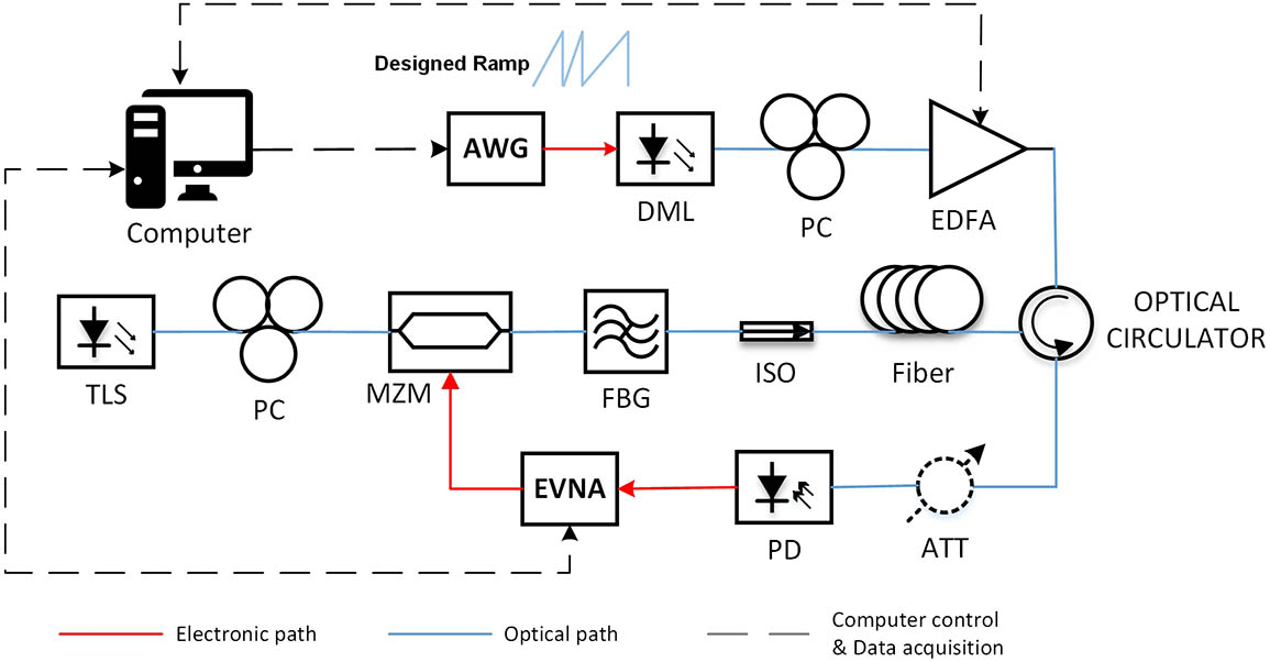
The experiment setup is shown in Fig. 1. There are two branches in our principle diagram: the pump branch on the top and the probe branch below.

Figure 1.Experimental setup for realizing the rectangular SBS filter. PC, polarization controller; AWG, arbitrary waveform generator; DML, directly modulated laser; EDFA, erbium-doped fiber amplifier; TLS, tunable laser source; MZM, Mach–Zehnder modulator; FBG, fiber Bragg grating; ISO, isolator; EVNA, electrical vector network analyzer; PD, photodiode; ATT, optical attenuator.
In the upper branch, a DML operating at is used for the pump light source. The pre-designed current waveform produced by a computer is sent into an arbitrary waveform generator (AWG). The current signal is used for directly modulating the semiconductor laser diode. By utilizing the chirp effect of DML, the spectrum of the pump light can be controlled precisely. The modulated pump signal is amplified by a high-power erbium-doped fiber amplifier (EDFA); then, it is sent into a single mode fiber (SMF) as the pump broadens. A polarization controller (PC) is used for maintaining the SBS gain at the maximum value.
In the probe branch, a swept signal covering bandwidths from 6 to 12 GHz is modulated on continuous wave (CW) light by a Mach–Zehnder modulator (MZM). The SBS gain area is within the sweeping range. Then, the high-frequency sideband of the probe light is suppressed by an FBG. The isolator (ISO) is used for preventing the pump light from damaging the tunable laser source (TLS) and MZM. The probe light and pump light propagate in opposite directions, and the swept sideband frequencies of the probe light that locate in SBS gain area are selectively amplified by SBS gain that is induced by the broadened pump light. Then, we adjust the average current waveform repetition period ranging from 2 to 100 ns. In order to investigate the effect of different fiber lengths, we choose three kinds of fibers with lengths of 0.2, 10.2, and 20.4 km. The filter shape can be precisely controlled by modifying the driving current based on the feedback compensation algorithm[18].
Figure 2 shows the relation between the in-band gain ripple and average current waveform repetition period at different fiber lengths, including 0.2, 10.2, and 20.4 km. We can find that for the average current repetition period that is either too short or too long, in-band gain ripples increase sharply, which will degrade the SBS filter performance. The low-ripple window located in the middle of the whole average repetition period range shows no more than a 2 dB ripple level. In order to investigate this area in detail, a zoom-in drawing of the low gain ripple area is shown in the inset of Fig. 2. According to the inset, we can find that in the low gain ripple area, the in-band ripples are similar for the three fiber length cases. The lower gain ripple for the 0.2 km fiber case is attributed to the lower gain level, because the lower gain level means smaller amplification multiples for the active filter, and tiny variations will be amplified in smaller multiples. Considering the light propagating time of in the 0.2 km fiber and filter bandwidth of , an approximately nanosecond (ns) level pump frequency sweeping period as well as an approximately gigahertz (GHz) level DAC bandwidth is needed for the external modulation scheme, while in the DML-based scheme, the optimal average current waveform repetition period between 9 to 13 ns corresponds to the DAC bandwidth of no more than 500 MHz, and there is no requirement for the frequency sweeping speed of the DAC. Obviously, the DML-based SBS MPF is with low cost and more suitable for the short fiber case.
Figure 2.In-band gain ripple and average current waveform repetition period relation with different fiber lengths of 0.2, 10.2, 20.4 km.
To better understand the filter performance difference during various average current waveform repetition periods, filter gain profiles are measured and shown as Fig. 3. Here, the SBS gain profile with fiber length is selected as an example.
Figure 3.Gain profile versus frequency at different current waveform repetition periods, including (a) 100 ns, (b) 33 ns, (c) 20 ns, (d) 14.29 ns, (e) 12.5 ns, (f) 10.53 ns, (g) 9.091 ns, (h) 8.33 ns, (i) 6.25 ns, (j) 5 ns, (k) 2.5 ns, and (l) 2 ns.
In Fig. 3, it can be seen that when the average current waveform repetition period is longer than 13 ns, the in-band gain ripple deteriorates dramatically. What is more serious is that SBS filter gain profile is not a rectangle anymore when the sweeping period equals 100 ns. While the repetition period is shorter than 5 ns, a strong peak appears at the center of the gain profile. In previous work[18], the repetition period at 10 ns is just an experienced value. By conducting this experiment, we notice that 10 ns is within the scope between 9 and 13 ns, and it is a reasonable value. To find out the reason for the SBS gain profile variation, the relation principle diagram between the driving current waveform and the chirped light spectrum of DML based on the direct modulation scheme is shown in Fig. 4.
Figure 4.Relation between temporal current waveform and chirped light spectrum of DML.
With the average current waveform repetition period becoming longer (as shown in the upper part of Fig. 4), the number of frequency components in the chirped light spectrum of the DML corresponding to different current amplitude ladders increases significantly when the sampling rates remain invariable for different temporal current waveform repetition periods, which means that more and more data are generated and require adjustments to maintain the rectangular filter shape. Then, massive amounts of data emerge, and the feedback algorithm does not work well due to limited calculation capability and relatively long data-acquisition time. On the contrary, with the decrease of the average current waveform repetition period, in other words, the repetition period is getting closer to the sampling period of the AWG we use, the spectrum line of the pump light is gradually moving to the middle of the whole sweeping frequency range. Finally, in the middle of the sweeping frequency spectrum, sharp peak with high power appears, resulting in high SBS gain ripple. Besides, a sharp decrease of repetition periods means that the effect of transient chirp cannot be neglected any more, which degrades the feedback effects at the same time.
Through the experimental results above, a huge difference can be observed in terms of SBS-MPF based on the direct modulation scheme[18] and external modulation scheme[13,15,19]. The SBS-MPF using DML as broadened pump shows more advantages compared with that using the external modulation scheme. In review of our work and previous work, the differences are listed as Table 1.
| Type | External modulation[13,15,19] | Direct modulation[18] |
|---|
| Key composition | Laser + electrical hybrid + IQ modulator + bias control + high sampling rate DAC | DML + low sampling rate DAC |
| Steep edges | Better selectivity | Slightly less steep |
| Bandwidth | Theoretic maximum at 1/2 DAC bandwidth | Limited by driving current amplitude range |
| Requirements for DAC | High bandwidth (double the filter bandwidth) | Relatively low bandwidth (always no more than 500 MHz despite the filter bandwidth) |
| High-frequency sweeping speed for short fibers | No requirements for sweeping speed |
| Application scenario | High precision | Cost sensitive |
| Narrow bandwidth | Wide bandwidth |
| Long fiber | Ultrashort fiber or waveguides |
Table 1. Comparison Between External Modulation Scheme and Direct Modulation Scheme
With the development of MPF towards integration, miniaturization, and automation, DML-based programmable SBS-MPF will be widely used in cost-efficient scenarios.
In conclusion, we realize an wide SBS-based rectangular MPF using a directly modulated pump and efficient feedback control algorithm. By changing the average current waveform repetition period, we measure the in-band ripples and SBS gain profiles. Replacing different lengths of fiber (including 0.2, 10.2, and 20.4 km) one by one, we can find that the SBS filter based on the directly modulated scheme shows better passband flatness within the repetition period window, ranging from 9 to 13 ns despite the fiber length. When the period is too long, massive data of spectrum components make it difficult to deal with feedback control, while transient chirp cannot be neglected, and chirped frequency elements are getting closer to the middle of the chirped light spectrum of DML for the too short current waveform repetition period. Both conditions are harmful for signal filtering. Unlike the external modulation scheme, the optimal current waveform repetition period is not related to the fiber length; therefore, the direct modulation scheme is more suitable for the short fiber scenario. Finally, experiment results provide a general guideline on the design of the SBS filter based on the DML scheme.
References
[1] J. Yao. J. Lightwave Technol., 27, 314(2009).
[2] M. Born, E. Wolf, A. B. Bhatia, P. Clemmow. Principles of Optics: Electromagnetic Theory of Propagation, Interference and Diffraction of Light(1970).
[3] J. Thuery. Microwaves: Industrial, Scientific, and Medical Applications(1992).
[4] G. Rizzoni, J. Kearns. Principles and Applications of Electrical Engineering(2004).
[5] J. Capmany, B. Ortega, D. Pastor. J. Lightwave Technol., 24, 201(2006).
[6] C. Wang, J. P. Yao. IEEE Photon. Technol. Lett., 25, 1889(2013).
[7] J. Palaci, G. E. Villanueva, J. V. Galan, J. Marti, B. Vidal. IEEE Photon. Technol. Lett., 22, 1276(2010).
[8] Y. T. Dai, J. P. Yao. Opt. Express, 16, 4713(2008).
[9] V. R. Supradeepa, C. M. Long, R. Wu, F. Ferdous, E. Hamidi, D. E. Leaird, A. M. Weiner. Nat. Photon., 6, 186(2012).
[10] B. Chen, E. H. Chan, X. Feng, X. Wang, B.-O. Guan. Chin. Opt. Lett., 15, 080604(2017).
[11] J. Gu, F. Wang, Y. Lu, M. Peng, L. Shi, C.-H. Lee. Chin. Opt. Lett., 15, 110603(2017).
[12] T. Tanemura, Y. Takushima, K. Kikuchi. Opt. Lett., 27, 1552(2002).
[13] W. Wei, L. Yi, Y. Jaouen, W. Hu. Opt. Express, 22, 23249(2014).
[14] H. Y. Jiang, D. Marpaung, M. Pagani, K. Vu, D. Y. Choi, S. J. Madden, L. S. Yan, B. J. Eggleton. Optica, 3, 30(2016).
[15] W. Wei, L. L. Yi, Y. Jaouen, M. Morvan, W. S. Hu. IEEE Photon. Technol. Lett., 27, 1593(2015).
[16] B. Vidal, M. A. Piqueras, J. Marti. Opt. Lett., 32, 23(2007).
[17] L. L. Yi, W. Wei, Y. Jaouen, M. Y. Shi, B. Han, M. Morvan, W. S. Hu. J. Lightwave Technol., 34, 669(2016).
[18] W. Wei, L. Yi, Y. Jaouen, W. Hu. Opt. Lett., 42, 4083(2017).
[19] W. Wei, L. Yi, Y. Jaouen, W. Hu. Sci. Rep., 6, 35621(2016).
[20] A. Zadok, A. Eyal, M. Tur. J. Lightwave Technol., 25, 2168(2007).
[21] E. Cabrera-Granado, O. G. Calderon, S. Melle, D. J. Gauthier. Opt. Express, 16, 16032(2008).
[22] M. Shi, L. Yi, W. Wei, G. Pu, W. Hu. IEEE Photon. J., 9, 7800308(2017).