
Jian-Xing Zhao, Jian-Lin Song, Yao Zhou, Rui-Long Zhao, Yi-Chao Liu, Jian-Hong Zhou. Multi-functional vanadium dioxide integrated metamaterial for terahertz wave manipulation[J]. Chinese Physics B, 2020, 29(9):
- Chinese Physics B
- Vol. 29, Issue 9, (2020)
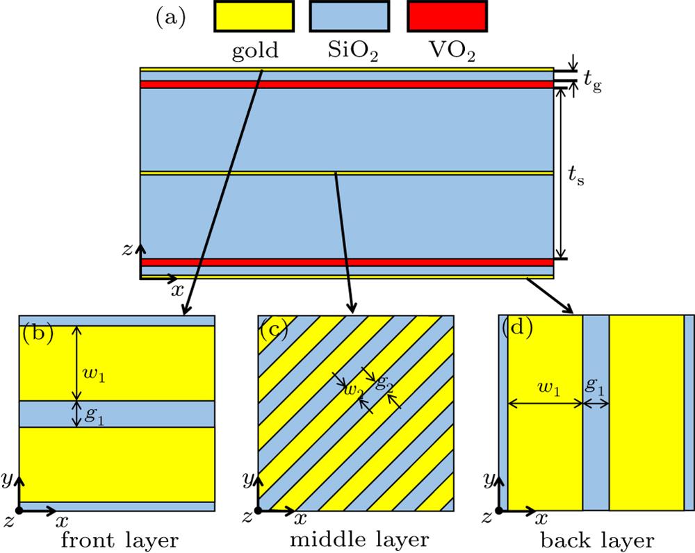
Fig. 1. (a) Cross section view of the proposed metamaterial. The thickness of the upper part is the same as that of the lower part. (b) Front, (c) middle, and (d) back metallic grating layers of the proposed metamaterial. The front grating is parallel to the x axis, the middle grating is oriented at 45° with respect to the x axis and the back grating is vertical to the x axis.
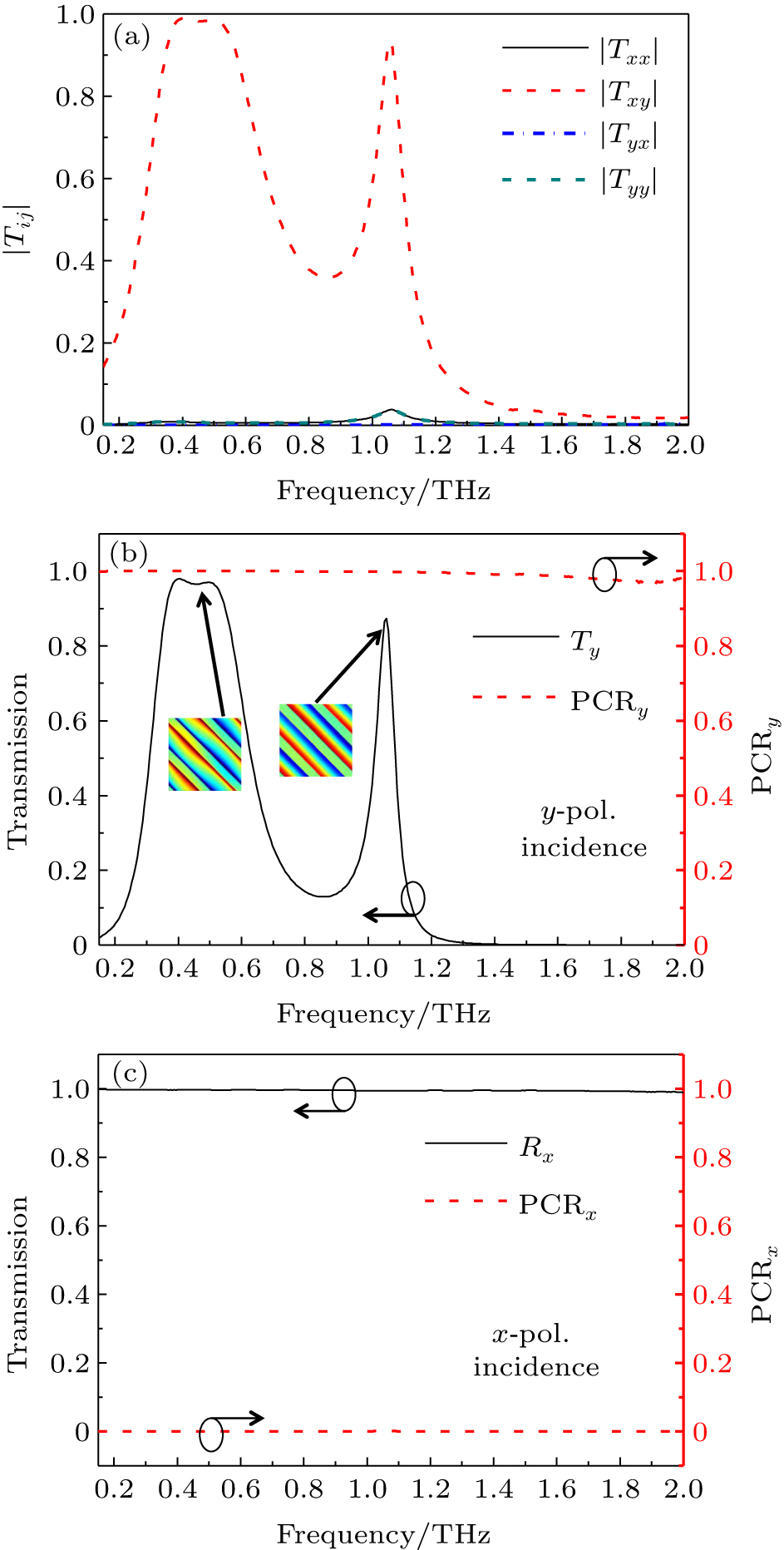
Fig. 2. (a) Moduli of the T matrix coefficients for forward propagation. (b) Transmission and PCR spectra for y -polarization (y -pol.) incidence. Insets are z -component electric field distributions in the middle x –y plane of the middle grating structure at the frequencies of 0.453 THz and 1.058 THz, respectively. (c) Reflection and PCR spectra for x -polarization (x -pol.) incidence.
Fig. 3. (a) Absorption spectrum for y -polarization incidence. (b) Reflection spectrum for x -polarization incidence. (c) The z -component electric field distribution in the x –y plane of the front grating layer, (d) the z -component electric field distribution in the y –z plane of the structure, and (e) the magnetic |Hx | field distribution in the y –z plane at the frequency of 1.155 THz when illuminated with y -polarized wave.
Fig. 4. (a) The absorption spectra with different t g when VO2 is at metal phase, and (b) the cross-polarization coefficient |Txy | with different t s when VO2 is at insulator phase for y -polarization incidence. (c) The absorption spectrum at metal phase and the cross-polarization coefficient at insulator phase for the optimized structure with w 1 = 56 μm, t s = 49 μm when illuminated with y -polarized wave. (d) The reflection spectra of the optimized structure with w 1 = 56 μm, t s = 49 μm at metal phase and insulator phase when illuminated with x -polarization wave.
Fig. 5. (a) The absorption spectra with different w 1 when VO2 is at metal phase, and (b) the cross-polarization coefficient |Txy | with different t s when VO2 is at insulator phase for y -polarization incidence. (c) The absorption spectrum at metal phase and the cross-polarization coefficient at insulator phase for the optimized structure with w 1 = 62 μm, t s = 56 μm when illuminated with y -polarized wave. (d) The reflection spectra of the optimized structure with w 1 = 62 μm, t s = 56 μm at metal phase and insulator phase when illuminated with x -polarization wave.
|
Table 1. The corresponding conditionsfor the three states.


Set citation alerts for the article
Please enter your email address

© Copyright 2018-2021 | Chinese Laser Press. All Rights Reserved 沪ICP备15018463号-20