Jing Li, Ze Hao, Li Pei, Tigang Ning, Jingjing Zheng, "Frequency-doubled triangular shape lightwave generation with a flexible modulation index," Chin. Opt. Lett. 15, 090603 (2017)
Copy Citation Text
An approach for full duty frequency-doubled triangle shape lightwave generation is proposed and demonstrated. It requires a dual-parallel Mach–Zehnder modulator (DP-MZM) driven by a sinusoidal signal. A stop band filter is coupled to filter out two undesired sidebands. By tuning the bias voltage applied to the DP-MZM, the output optical intensity with a full duty cycle triangle shape profile can be obtained. It is found that the required modulation index is no longer a fixed one. It can vary within a range, without degrading the target waveform. The principle is analyzed by theory and evaluated by simulation. A proof-of-concept experiment is also conducted. Good agreements between theoretical prediction and experimental results have been found. This approach might be attractive due to the feature of a variable modulation index, which insures simple operation in practice.
Photonic generation of optical arbitrary waveform signals has been a topic of interest recently that has found various applications in microwave photonic systems, microwave, or high-speed all-optical signal processing and manipulation[1–3]. The triangle-shaped waveform, which is featured with its linearly raising and falling edge in optical intensity, has lots of advantages over any other waveform. For instance, compared with the Gaussian profile, the triangular-shaped light wave offers a more than two-fold increase in average efficiency in all-optical wavelength conversion[4]. The triangular shape light wave has also been reported as a better choice for all-optical converting, optical pulse compressing, and signal copying[5–7]. So far, various technologies have been proposed to generate triangular waveform signals in the optical domain. One method based on optical-spectrum-shaping combined with frequency-to-time mapping has been reported by several groups[8]. Another alternative approach that achieves a high-quality triangular-shaped profile is reported based on external modulation of a continuous-wave laser. The key point is to manipulate the harmonics of optical intensity approximately equal to the first and third-order Fourier components of an idea triangular waveform. In this scheme, a full-duty cycle signal can be easily obtained. Normally, it can be achieved by using external modulation with a specific modulation index. Different modulators can be employed. For example, a triangular-shaped waveform signal can be generated by using a dual-electrode Mach–Zehnder modulator (MZM) followed by a dispersive element[9] or a polarization multiplication unit[10]. In Ref. [11], a polarization modulator in a Sagnac loop is also utilized to generate triangular-shaped waveforms and arbitrary waveforms. A triangular-shaped light wave can also be generated by using a dual-parallel MZM (DP-MZM) with a 90° electrical hybrid coupler[12], or driven by two RF signals with fundamental and triple the frequency[13], or followed by a bandpass optical filter[14]. However, all the above schemes require a specific modulation index, or multiple modulation indices with a specific relationship, which limit the flexibility and applications in practice.
In this work, we propose and demonstrate a full-duty triangular-shaped light wave generator based on a DP-MZM followed by an optical filter. By tuning the bias voltage applied to the modulator, optical intensity with its expression approximately close to the Fourier expression of an ideal triangular-shaped waveform can be obtained. Different from the approach in Ref. [14], the problem of modulation index dependence can be solved in this work. Normally, the modulation index in our case is no longer a fixed one. It can vary within a range, without degrading the target waveform. The exact properties will be discussed by simulation and verified by experiment.
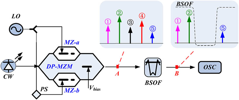
The schematic diagram of the proposal is shown in Fig. 1. A CW laser with an angular frequency of is modulated by a sinusoidal signal with angular frequency , exploiting a DP-MZM to generate a signal with multiple modulation sidebands. In detail, the RF sinusoidal signal is first split by an electrical hybrid coupler and then drives two sub-MZMs. In our case, the phase difference is introduced by a phase shifter (PS) placed on the lower path. Here, the bias of the two child MZMs (MZ-a and MZ-b) are set at its maximum transmission point (MATP), which means only even-order sidebands can be found in the spectral diagram.
Sign up for Chinese Optics Letters TOC. Get the latest issue of Chinese Optics Letters delivered right to you!Sign up now
Figure 1.Schematic diagram of a triangular-shaped light wave generator (spectra diagram inserted).
The optical field at the output of the DP-MZM (Point A) is: where is the magnitude of the optical carrier, is the modulation index, is the RF modulating electrical voltage, denotes the half-wave switching voltage of the DP-MZM, represents the phase shift induced by the PS, and is the bias voltage () induced phase shift applied to the parent MZM. In Eq. (1), the first two terms represent the optical field at the upper path of DP-MZM. The rest of the terms denote the optical field at the lower path. By expanding Eq. (1), becomes where is the magnitude of each sideband, and is the Bessel function of the first kind of order . Equation (2) shows that all odd-order sidebands are suppressed, i.e., number. In principle, the sidebands ①∼⑤ in Fig. 1 (Point A) represent the five modulation sidebands with orders of , , carrier, , and . To obtain these five primary sidebands, there is basic requirement of the modulation index . Figure 2 illustrates the relationship between and . As shown in this figure, the modulation index is defined within a range of . Normally, cannot be too small or too big. For example, if is smaller than 1, the impact of the -order sidebands will not be high enough to contribute to the waveform. But when is too big (, for example), the -order sidebands will affect the profile of the optical intensity, which may lead to waveform distortion. In our case, we only consider optical sidebands no bigger than order, in other words , , 0, 2, 4 in Eqs. (2) and (3).
Figure 2.Relationship between the magnitude of and the modulation index .
Then the light wave is coupled into a band stop optical filter (BSOF, as shown in Fig. 1), to remove the interference sidebands (sidebands ③ and ④). Thus, the output spectrum only consists of sidebands ①, ②, and ⑤, as shown in Fig. 1 (Point B). The corresponding optical field becomes:
Then the optical intensity of as a function of can be concluded as where represents a high-order harmonic, which can be neglected within the variable range (). It is well known that the Fourier expansion of an ideal triangular-shaped waveform is given by
Comparing the expression of in Eq. (5) with the triangular-shaped waveform expression in Eq. (6) [substitute into Eq. (6)], an approximation can be made between the desired harmonics of and the first two terms of . Therefore, the following relationship should be satisfied,
Substituting and into Eq. (7) and solving the equation, we can obtain the relationship between and as:
Note that there is no requirement on the modulation index in Eq. (8), which means can be chosen randomly within the range . Since no specific modulation index is needed, the parameter setting will be more effective and easy. Figure 3 plots the relationship between the PS phase shift and bias-induced phase shift according to Eq. (8). To obtain an approximate triangular-shaped waveform, these two parameters should be properly aligned. From Eq. (8), the PS phase shift can be widely chosen except for some special value (i.e., 0°, 45°, 90°...).
Figure 3.Relationship between the bias-induced phase shift and the PS phase shift at different ranges: (a) ; (b) ; (c) ; (d) .
Thus, the whole 0°–180° range is separated into four sections [in Figs. 3(a)–3(d)]. As shown in these figures, for a given (i.e., , 75°, 124°, 150°), is supposed to be aligned (i.e., , 108.4°, 324.2°, 49.6°) accordingly. This feature might be useful since in practice the RF PS or hybrid coupler cannot be perfectly designed due to the poor regulating accuracy or limited bandwidth. Therefore, we do not need to adjust the continuously. In fact, we can fix at first and then align according to Fig. 3. Practically, tuning the bias voltage is a much simpler and easier way since the bias voltage stabilizing circuits are commercially available. When the above two parameters ( and ) are set, the power ratio between sidebands ① and ⑤ is roughly 19 dB, which corresponds to the magnitude relationship in Eq. (8).
We conduct a simulation via Opti-system 10.0, to evaluate the performance. As shown in Fig. 1, a light from a CW laser source at a wavelength of with an output power of 20 dBm is coupled to a DP-MZM. The DP-MZM has an insertion loss of 5 dB, and RF and DC half-wave switching voltages of 4 and 10 V, respectively. The DC-bias of two child MZMs (MZ-a and MZ-b) is set to the MATP. An RF signal is first power split into two paths and then drives the two child MZM. At the lower path, a PS is connected to introduce a constant phase shift . Since the modulation index can be set randomly, we may fix with the same value () as in Ref. [14]. Then, to validate the relationship in Fig. 3, the PS phase shift and bias-induced phase shift is set as 18° and 264°, respectively. After the DP-MZM, a BSOF is connected to remove the interference sidebands (③ and ④). Taking , for example, the output optical spectrum is shown in Fig. 4(a). Note that the power ratio between sidebands ① and ⑤ is roughly 19 dB, which agrees well with the prediction in Eq. (8). The corresponding temporal waveform is shown in Fig. 4(b). As can be seen, a 20 GHz triangular-shaped light wave is successfully generated by using a 10 GHz sinusoidal oscillator. The electrical spectrum can also be obtained via a photodiode followed by an electrical spectrum analyzer. As shown in Fig. 4(c), the spectrum mainly consists of the 2nd-order harmonic at 20 GHz and the 6th-order harmonic at 60 GHz. The 6th-order harmonic is around 19 dB lower than the 2nd-order one (), which also agrees well with the prediction. Moreover, the undesired harmonics are well suppressed and can be neglected.
Figure 4.Generation of a 20 GHz triangular-shaped lightwave using a 10 GHz sinusoidal oscillator at and . (a) The optical spectrum; (b) the generated 20 GHz triangular waveform; (c) the electrical spectrum after photodiode detection.
In this work, the setting of the PS phase shift is flexible. Except for some special values (i.e., 0°, 45°, 90°,...), can be chosen randomly. As a proof, Figs. 5(a)–5(i) illustrate the other three cases in Fig. 3: (1) , , (2) , , and (3) , . As shown in the figures, for different , the spectra [Figs. 5(a), 5(d), and 5(g)] may have slight differences, but the power ratio between sidebands ① and ⑤ remains 19 dB. The corresponding waveform [Figs. 5(b), 5(e), and 5(h)] is still triangular shaped. As to the electrical spectra [Figs. 5(c), 5(f), and 5(i)], the target also stays the same. Therefore, we have proven that the PS phase shift can be chosen flexibly. To obtain a triangular-shaped waveform, we only need to align the bias voltage applied to the parent MZM.
Figure 5.Simulation results (optical spectrum, temporal waveform, and electrical spectrum) of triangular-shaped light wave generation at different and ; (a) (b) (c) and ; (d) (e) (f) and ; (g) (h) (i) and .
Next, we will compare our work with the prototype in Ref. [14] since we share a similar architecture (DP-MZM followed by an optical filter). Here, we conduct these two approaches under the same simulation environment and then make a fair comparison. Figure 6 plots the simulation results using the parameters in Ref. [14]: driving frequency of 10 GHz, and modulation index of 1.51. The simulation results agree well with the experimental ones in the reference. As shown in Fig. 6(a), the optical spectrum is similar to that of optical single sideband modulation. The power ratio of the 1st and 3rd order sidebands is around 19 dB. The corresponding temporal waveform can be found in Fig. 6(b). The first difference can be clearly observed: the repetition rate of the generated triangular-shaped light wave is 10 GHz [in Fig. 6(b)], but in our case [in Fig. 4(b)] a 20 GHz repetition rate can be obtained, which means a high-speed triangular-shaped light wave can be generated by using the same components. The electrical spectrum also proves the theory. As shown in Fig. 6(c), it mainly consists of the fundamental tone at 10 GHz and the third-order harmonic at 30 GHz. The third-order harmonic is around 19 dB lower than the fundamental one ().
Figure 6.Generation of a 10 GHz triangular-shaped light wave using a 10 GHz sinusoidal oscillator in Ref. [14]. (a) The optical spectrum; (b) the generated 10 GHz triangular waveform; (c) the electrical spectrum after photodiode detection.
The second difference is that we do not need a fixed or specific modulation index. To prove this theory, Fig. 7 shows the power ratio of two approaches when the modulation index is tuned within the range of . Note that the left and the right vertical axes in Fig. 7 are different. In theory, the triangular-shaped waveform is determined by the 1/9 magnitude ratio of the and terms in Eq. (7). When converted to optical intensity, this ratio is around 19 dB. In our case, this relationship is . But in Ref. [14], it becomes . As shown in the figure, the principle of Ref. [14] is strictly dependent on . When fluctuates from the optimum value , the power ratio changes dramatically. As to this proposal, when increases, the power ratio almost remains constant. The slight difference may be induced by the interference harmonic and system noise. Therefore, we have proven that the modulation index can also be chosen flexibly.
Figure 7.(Color online) Power ratio of two approaches at different modulation index values. Optical spectrum; the left axis stands for in this work and the right axis stands for in Ref. [14].
Figures 8(a)–8(f) shows the simulated results at different driving frequency as: (a)(b) ; (c)(d) ; (e)(f) . Note that for different repetition rates (30, 40, and 50 GHz), the generated signal is still with a triangular-shaped waveform. Benefitting from the flexible modulation property, an ideal triangular-shape waveform with any repetition rate can be obtained by adjusting the driving frequency.
Figure 8.Triangular-shaped light wave generation with different repetition rates (temporal waveform and corresponding electrical spectrum): (a)(b) 30 GHz; (c)(d) 40 GHz; (e)(f) 50 GHz.
A proof-of-concept experiment based on the setup in Fig. 1 is demonstrated. A CW light at 1555.26 nm from the LO (Agilent 8164A) is sent to the DP-MZM (Fujitsu FTM7962EP) for modulation. This modulator is characterized by a low RF and a relatively high DC . Normally, a high DC means the bias drift problem is very limited. The signal generator (Hewlett 83711B) generates a 10 GHz sinusoid signal as the driving signal. Then the 10 GHz signal is split into two paths by a RF hybrid coupler. Instead of using a tunable RF phase shifter, two time delay lines (TDLs) are embedded on both paths since there is no PS in our lab. Because the phase difference in our case can be set randomly, except for some special values (i.e., 0°, 45°, 90°...), we do not need to know the exact time delay induced by the TDL. The two path signals are then amplified and coupled to the RF ports. There might be insertion loss of the hybrid coupler, microwave line, and TDL, which will degrade the modulation index . In our case, these faults will not matter at all. We only need to make sure that is big enough to generate five major sidebands in the optical spectrum, as shown in Fig. 9(a). In the experiment, the bias voltages applied to two child MZMs are aligned manually. Odd-order sidebands exist in the spectrum, which can be minimized by using a bias controlling circuit. Then the interference sidebands (③, ④, and odd-order sidebands) are removed by using a BSOF. In our case, a standard 50/100 GHz optical interleaver (OI) is employed as the BSOF. The response of the OI is given by Fig. 9(b) (dashed line). Figure 9(b) also plots the output spectrum after the OI. Note that only three major sidebands exist in the spectrum (①, ②, and ⑤). By carefully aligning the bias voltage applied to the parent MZM, the power ratio between sidebands ① and ⑤ can reach 19 dB.
Figure 9.(a) Optical spectrum at the output of DP-MZM and (b) optical spectrum after the OI (the response of the OI is given by the dashed line).
At the output of the OI, a triangular-shaped waveform is obtained, as shown in Fig. 10(a). Obviously, the intensity profile is very close to the simulation results. The zoom-in view [in Fig. 10(b)] is very close to an ideal triangular shape, which agrees well with the prediction. During the experimental measurement, the phase difference and modulation index can be variable. The only parameter we need to properly align is the bias voltage applied to the parent MZM.
Figure 10.(a) Waveform of optical intensity; (b) zoom-in view (the ideal triangular-shaped waveform is given by the dashed line).
In conclusion, we propose and demonstrate a photonic approach to generating frequency-doubled triangular-shaped light waves using a DP-MZM followed by a BSOF, which can be replaced by a fiber grating. Different from the previous research based on external modulation, the proposal requires no specific or fixed modulation index, which guarantees the flexibility of the generator. Except for the modulation index, the phase shift applied to the DP-MZM is also variable. By carefully adjusting the bias voltage applied to the parent MZM, a triangular-shaped waveform can be obtained in the optical intensity. The stability of the generator can be further improved by using a high-precision voltage stabilizing circuit. Note that there are power differences in temporal waveforms and optical signal-to-noise ratio differences in the electrical spectrum for different and (as shown in Fig. 5), due to the phase calculation of magnitude in Eq. (3). Normally, when the PS phase shift is set within the range of and , light waves with a relatively higher power can be obtained. Increasing the modulation index can also enhance the power level.
Sign up for Chinese Optics Letters TOC. Get the latest issue of Chinese Optics Letters delivered right to you!Sign up now
References
[1] J. Li, T. Ning, L. Pei, J. Zheng, J. Sun, Y. Li, J. Yuan. Chin. Opt. Lett., 13, 080606(2015).
[2] H. Chen, T. Ning, J. Li, L. Pei, J. Yuan, X. Wen. Chin. Opt. Lett., 15, 060605(2017).
[4] F. Parmigiani, M. Ibsen, T. T. Ng, L. A. Provost, P. Petropoulos, D. J. Richardson. 2008 Optical Fiber Communication Conference (OFC’08), OMP3(2008).
[5] R. S. Bhamber, A. I. Latkin, S. Boscolo, S. K. Turitsyn. 34th European Conference on Optical Communication (ECOC 2008), Th.1.B.2(2008).
[6] A. I. Latkin, S. Boscolo, R. S. Bhamber, S. K. Turitsyn. 34th European Conference on Optical Communication (ECOC 2008), Mo.3.F.4(2008).