1Shandong Key Laboratory of Optical Fiber Sensing Technologies, Laser Institute, Qilu University of Technology (Shandong Academy of Sciences), Jinan 250014, China
2School of Electrical Engineering and Telecommunications, The University of New South Wales, NSW 2052, Australia
3College of Precision Instrument and Opto-Electronics Engineering and Key Laboratory of Opto-Electronics Information and Technical Science, Ministry of Education, Tianjin University, Tianjin 300072, China
We present a high-sensitivity fiber Bragg grating (FBG)-based microphone with a flat response and static pressure equalization. A very high dynamic sensitivity of the microphone is achieved by a pressure sensing structure based on a carbon fiber diaphragm. Static pressure equalization is realized by a balance structure with a capillary glass tube. The resonances of the sensor are suppressed by air damping structures, and a broadened flat response is achieved. An acoustic-solid interaction model was used to analyze the response characteristics of the microphone. An experimental prototype was produced and tested, and the results are well consistent with the design. The tested sensitivity was 10 dB re 1 pm/Pa from 10 Hz to 2.5 kHz with a fluctuation of less than ±1.5 dB. Combined with the phase-generated-carrier-based coherent detection scheme, the microphone can achieve a sound resolution of the milli-pascal level. The static pressure sensitivity is measured to be 0.27 pm/atm, which is 100 dB lower than the dynamic sensitivity.
Optical microphones are of interest because they are immune to electro-magnetic interference, suitable for remote sensing, electrically passive, and they can offer multiplexing advantages over electronic systems. There are several kinds of optical microphone solutions, including fiber Bragg grating (FBG)[1,2] or fiber laser[3,4]-based microphones, Fabry–Perot fiber-optic microphones[5–7] and fiber-optic interferometrics[8,9]. The fiber grating types have the advantages of simple structure, low cost, and strong multiplexing capability and can achieve high sensitivity and reliability through a simple diaphragm sensing structure[1,2]. It has been reported that a sensitivity on the order of ε can be achieved by attaching an FBG device to a polyethylene terephthalate (PETP) polymer diaphragm transducer[2], and a very high sensitivity of re (ε) has been demonstrated by attaching a fiber laser to a diaphragm with a diameter of 44 mm[4].
Although these designs can achieve extremely high sensitivity, FBG microphones (FBGMs) with flat response covering the human voice frequency have been barely reported. In addition, due to the extremely high sensitivity, static pressure changes can have a large impact on the performance of the sensor. The static pressure may vary with an amplitude of a few hundred pascal (Pa) due to the daily variation of the atmospheric pressure or variation with the measurement altitude. Annual pressure change may reach tens of hundred Pa[10], corresponding to several thousand micro-strain changes of the fiber in the microphone, which is likely to cause mechanical failure.
In this Letter, we propose an FBG-based microphone with very high sensitivity, as well as static pressure equalization. We firstly use the lumped parameter model to analyze the response characteristics of the microphone, and then use the finite-element method to simulate and optimize the structural parameters. The sensor prototype was demonstrated to have a high sensitivity and flat response from 5 Hz to 2.5 kHz. The static pressure sensitivity was measured to be 100 dB lower than the dynamic sensitivity.
Sign up for Chinese Optics Letters TOC. Get the latest issue of Chinese Optics Letters delivered right to you!Sign up now
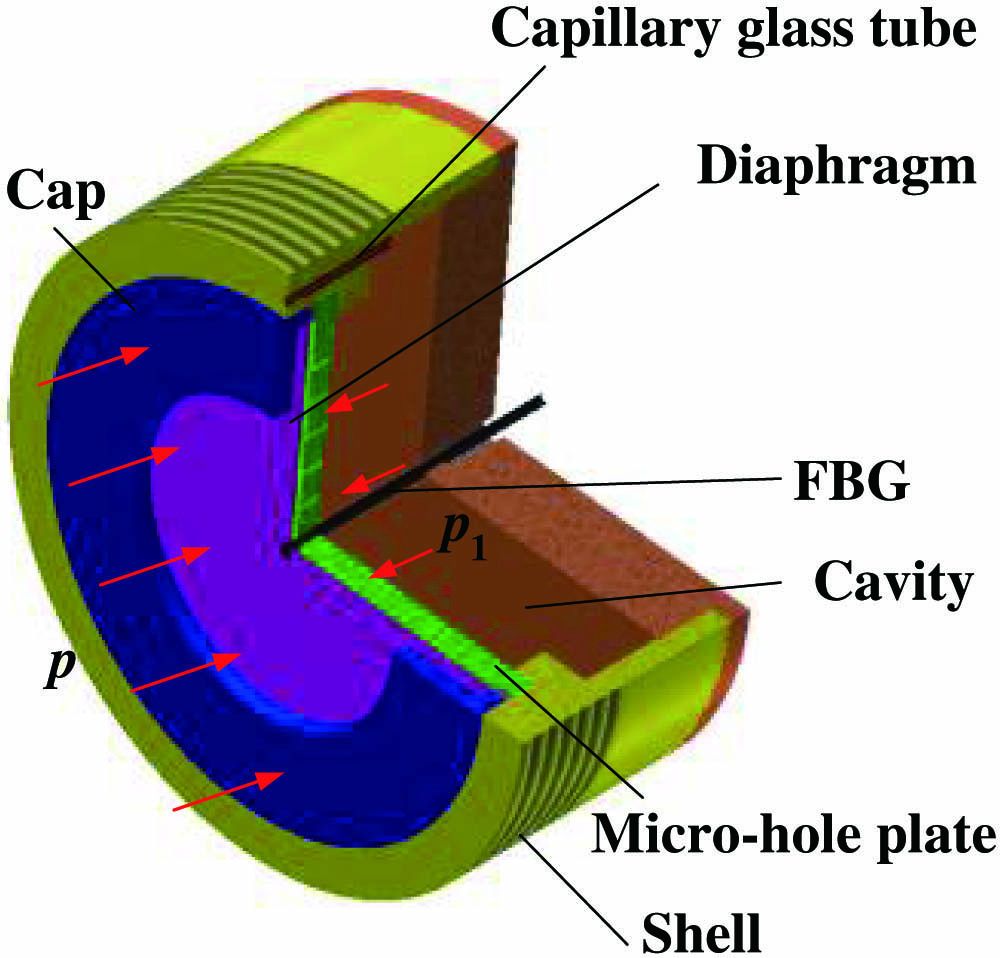
The configuration of the proposed microphone is shown in Fig. 1. The sensor consists of a metal shell, a diaphragm embedded in the shell, and an FBG connected to the center of the diaphragm by epoxy glue. A cylindrical cap is connected to the shell and compacted with the diaphragm. The cap has an acoustic hole, and acoustic pressure can couple inside the sensor shell through the hole and act on the surface of the piston-like diaphragm. The diaphragm, which is made of a plate with uniform thickness, is pressurized in the axial direction, inducing an axial tension strain change in the bare FBG, which is attached perpendicularly to the plane of the diaphragm.
A micro-hole plate is mounted behind the diaphragm, as a damper for suppressing the resonances of the diaphragm. The damping is caused by the movement of air in the slit and the micro-hole behind the diaphragm. Static pressure equalization is realized by communicating the inside cavity of the microphone to the exterior space by a capillary glass tube. Suppose the sensitivity of the microphone without the capillary glass tube is , which is defined as the FBG wavelength change due to the unit acoustic pressure. When there is a capillary glass tube in the microphone, part of the acoustic pressure can pass through the capillary tube and act on the back of the diaphragm. The diaphragm deforms under the pressure differentials. Define pressure transfer function as , where is the acoustic pressure in the cavity, and the sensitivity of the microphone with a capillary glass tube can be written as
Assuming that the diaphragm size is much smaller than the acoustic wavelength, we use lumped parameter models to calculate the pressure transfer function. Figure 2(a) shows the acoustic model of the microphone, and Fig. 2(b) shows the electric-circuit element analogous to the acoustic model. According to the theory of circuit analysis, the magnitude of can be expressed as where and are the acoustic mass and the equivalent acoustic resistance of the capillary glass tube, respectively; is the equivalent acoustic compliance of the cavity; is the frequency of the acoustic wave. , , and are given by[11]where is the density of the air, is the kinematic viscosity, is the angle frequency of the acoustic wave, and is the acoustic velocity.
Figure 2.(a) Acoustic model of the FBGM and (b) electric-circuit element analogous to the acoustic model, where and are the length and the internal radius of the capillary glass tube, respectively, and is the volume of the cavity.
Thus, the pressure transfer function can be written as where
Figure 3(a) gives a typical example for the magnitude of . It can be seen that the microphone has a high-pass response. We define as the cutoff frequency.
It is easy to know from the expression of the resonant frequency of Eq. (3a) that, for a certain , increasing the volume of the cavity, decreasing the diameter of the tube, and increasing the length of the tube all reduce the cutoff frequency. Above the cutoff frequency, , the transfer function has no effect on sensitivity.
The sensitivity can be calculated by the thin circular plate deformation model under uniform pressure and central concentrated load . The displacement at the center of the diaphragm under uniform pressure is given by[12]where is the flexural rigidity of the diaphragm, and is the radius of the diaphragm.
The displacement at the center of the diaphragm caused by the central concentrated load is[12]
The strain of the fiber under the concentrated load can be expressed as where is the cross section area of the fiber, and is the Young’s modulus of the fiber. For a common single-mode fiber, , .
From the geometric relationship, the strain of the fiber can be written as , where is the fixed length of the FBG; in combination with Eqs. (4)–(6), we get the strain of the fiber caused by the unit acoustic pressure as
The FBG wavelength change induced by the strain can be written as where is the effective photoelastic constant of the fiber, and is the Bragg wavelength of the FBG.
In this Letter, we use a carbon fiber diaphragm with a thickness of 0.2 mm, a Young’s modulus of , a radius of , and an FBG with a fixed length of 15 mm. It can be calculated that . If the capillary glass tube has a length of 5 mm, an internal diameter of 0.2 mm, and the cavity volume is , a cutoff frequency of can be obtained.
Finite-element models are developed to provide a more precise simulation of the response of the microphone. We use an acoustic-solid interaction model to simulate the acoustical transmission in the microphone and the strain in the fiber. The analysis is carried out within the frequency range of 0.5–10 kHz, which covers the human voice frequency. The simulation yields the strain distribution along the optical fiber. The strain components evaluated at the midpoint of the FBG are then used in the optical model to calculate the Bragg wavelength shift according to Eq. (8).
The simulated results are shown in Fig. 4, where 0 dB is defined as 1 pm/Pa. The dashed line is the response without damping, and the solid line is the response with damping, where the area in the capillary glass tube and the micro-hole is treated with a narrow region acoustic model, and the dynamic viscosity of the air is in the simulation. It can be seen that damping flattens the low-frequency and high-frequency responses of the microphone, and the sensor can get a flat frequency response from 5 Hz to 5 kHz.
The colored acoustic pressure amplitude profiles reveal the transmission characteristics of acoustic waves at, below, and above the cutoff frequency, respectively. It can be seen that, below the cutoff frequency, the acoustic pressure can pass through the capillary glass tube, resulting in pressure equalization on both sides of the diaphragm; on the contrary, above the cutoff frequency, the acoustic pressure is greatly attenuated in the capillary glass tube, and the diaphragm deforms under the unilateral acoustic pressure. This is the principle of static pressure equalization achieved by the sensor structure proposed in this Letter.
In order to provide a full characterization of the microphone performance, we also carry out a parametric analysis of the low-frequency responses of the microphone by varying the internal radius of the capillary glass tube. The simulation results are shown in Fig. 5. It can be seen that the cutoff frequency decreases with the decrease of the internal radius of the capillary glass tube. A flat response curve of even down to 1 Hz can be obtained, with a capillary glass tube with an internal radius of 0.1 mm.
Figure 5.Simulated responses of the microphones with capillary glass tubes of different internal radii.
Figure 6 shows a photograph of a microphone prototype. The sensor has a capillary glass tube for static pressure equalization, and the tube has a length of 5 mm and an internal diameter of 0.2 mm. The FBG in the microphone has a grating length of 10 mm and a full width at half-maximum (FWHM) of 0.21 nm.
The dynamic performance of the FBGM was measured by comparing the output to that of a calibrated reference microphone (RM) located in close proximity to the sensor in an acoustic field generated by a nearby speaker, as shown in Fig. 7. The RM has a sensitivity of 38 mV/Pa and a flat response up to 20 kHz. High-resolution dynamic wavelength demodulation of the FBG can be achieved by the interferometric method[13] with an amplified spontaneous emission (ASE) source. The Michelson interferometer has a path imbalance of 5 mm. The wavelength shifts are converted to phase shifts by using the interferometer, which can be expressed as where is the effective refractive index of the fiber, and is the path imbalance of the interferometer. The phase shifts obtained by demodulation can be calibrated to wavelength shifts by Eq. (9). A piezoelectric (PZT) fiber stretcher in one of the interferometer arms was used to induce a phase-shift carrier signal of 5 kHz on the sensor output signals to enable passive recovery of dynamic phase-shift information using phase generated carrier (PGC) demodulation. A dynamic resolution of [14,15] can be realized in the frequency range up to 2.5 kHz. In this system, FBGMs of different wavelengths can be multiplexed by a pair of dense wavelength division multiplexers (DWDM).
The static pressure sensitivity was tested with the microphone installed within a closed cavity fed by an air pump. The air pressure in the closed cavity was calculated by a barometer. The pressure-induced FBG wavelength shift was monitored by an optical spectrum analyzer.
The sensor displays a flat response of re pm/Pa over the frequency band from 10 Hz to 2.5 kHz, with a fluctuation of less than , as shown in Fig. 8, which is slightly lower than the theoretical value. This may be because the optical fiber and the sensor structure are bonded by epoxy bonding, which does not satisfy the ideal rigid condition. Combined with the demodulation scheme, it can be estimated that the microphone can achieve an equivalent acoustic noise of the milli-Pa (mPa) level. Potentially, the resolution of the system can be further improved to be better than by using a narrow linewidth fiber laser and an interferometer with long path imbalance[16–19], thereby reducing the equivalent acoustic noise to the order of micro-Pa (μPa).
The static pressure test result is shown in Fig. 9(a), compared with the linear response of wavelength shift with dynamic pressure amplitude of 1000 Hz, which is shown in Fig. 9(b). The fitted linear response of the wavelength shift to static pressure suggests a static pressure sensitivity of of the sensor over the pressure range from to 10 atm, which is 100 dB lower than the dynamic pressure sensitivity in amplitude. Thus, the results indicate that the hydrophone has a static pressure equalization feature.
Figure 9.(a) Wavelength shift versus static pressure and (b) wavelength shift versus dynamic pressure amplitude of 1000 Hz.
The temperature sensitivity and directivity of the microphone were also tested and are shown in Figs. 10 and 11. In contrast, the temperature sensitivity of a bare fiber grating was also tested. It can be seen that the microphone has a temperature sensitivity of 21 pm/°C and has omnidirectional characteristics.
Figure 10.Tested temperature sensitivity of the fiber microphone.
In conclusion, we presented a novel FBG-based microphone of very high dynamic sensitivity and static pressure equalization. The very high sensitivity is achieved by an acoustical sensitivity enhancing structure based on carbon fiber diaphragm. Static pressure equalization is realized by a balance structure with a capillary glass tube. Based on simulation analysis and optimization of the microphone, an experimental prototype was made and demonstrated to have a high sensitivity of re 1 pm/Pa and a flat response from 10 Hz to 2.5 kHz. The static pressure sensitivity was measured to be 100 dB lower than the dynamic sensitivity. This technology enables FBGMs with very high sensitivity to work in environments with large static pressure variations.