Jiakun Li, Qibo Feng, Chuanchen Bao, Bin Zhang. Method for simultaneously and directly measuring all six-DOF motion errors of a rotary axis[J]. Chinese Optics Letters, 2019, 17(1): 011203
Copy Citation Text
We report a method for simultaneously and directly measuring all six-degrees-of-freedom (six-DOF) motion errors of a rotary axis. Such a method combines the principles of laser interferometry and laser collimation measurement. One reference rotary axis and two retro-reflectors are used to achieve simultaneous sensitivity to all six errors in a full-circle measuring range. As no separation models are required, our method is capable of dynamically measuring these errors in real time and conveniently determining the origin of the errors. An automatic measuring device is built. The effectiveness of our method is experimentally demonstrated.
The rotary axis is the key component of various types of equipment, especially for the five-axis computer numerical control (CNC) machine tool. Nowadays, errors occurring during the manufacturing process of high-value components using the CNC machine tools are not acceptable in many high-technology industrial fields, such as aerospace, automobiles, shipbuilding, and large science facilities. To obtain accurate components, the demand for high-precision and high-efficiency measurements has continuously increased. Accordingly, the manufacturing process could be optimized by using feedback data[1]. It has been verified that the machining accuracy can be greatly improved after compensating for the errors. For the five-axis CNC machine tool, the motion errors of the rotary axes have critical effects on its machining accuracy and must be measured accurately and efficiently.
When an axis rotates around the axis, there are six-degrees-of-freedom (six-DOF) motion errors, including the angular positioning error around the axis , radial motion errors along the axis and axis , axial motion error along the axis , and tilt motion errors around the axis and axis [2]. To measure these errors, various methods have been proposed by researchers, which can be classified into two categories: “direct” and “indirect” measurement methods. Indirect measurement, such as ball bar tests, R test, probing of artifacts, tracking interferometer, and machining tests, focuses on the tool tip location as the superposition of multiple single errors[3,4]. Therefore, these methods require detailed error models and best-fitting algorithms to separate each axis or to identify each error, which leads to a large amount of calculation, and thus, it is difficult to measure errors in real time[5]. In addition, indirect measurement has limitations in terms of measurable dimensions and measurable positions[3]. Some of these methods, such as ball bar tests and R test, even lack the capability of measuring the angular positioning error, which is one of the most important parameters of a rotary axis. Therefore, the advantages of direct measurement, such as the convenience of determining the origin of the error and the capability to implement online or in-process measurement, are particularly significant. However, efficiency is a critical issue for direct measurement, as most direct measurement methods can measure only one error at a time[6–11]. In recent years, methods for simultaneously measuring several errors have been proposed by researchers[12–16]. To measure all the six-DOF motion errors, several steps are required for some methods. For example, Park et al. used reflection gratings and position-sensitive detectors (PSDs) to measure all six-DOF motion errors through two steps[17]. The dual optical path measurement method proposed by He et al. can measure all six-DOF motion errors through five steps[18]. However, the problems of excessive time consumption and labor intensity still exist. It is difficult to ensure the accuracy of the measurement, owing to the change in the environment and the adjustment of the accessories between different steps. To the best of our knowledge, there is no simultaneous measurement method that can directly measure all six-DOF motion errors of a rotary axis.
In this Letter, a method for simultaneously and directly measuring all six-DOF motion errors of a rotary axis is proposed. Such a method combines the principles of laser interferometry and laser fiber collimation measurement based on our previous research on the measurement of five-DOF motion errors[19]. Two retro-reflectors (RRs) were used as the error-sensitive unit. For one of the RRs, a beam-splitting film was coated on half of its bottom surface. Thus, the error-sensitive unit can be simultaneously sensitive to all six-DOF motion errors. A reference rotary axis was used to extend the measuring range to 360° and ensure the interference measurement by making it servo-track the rotation of the target rotary axis.
Sign up for Chinese Optics Letters TOC. Get the latest issue of Chinese Optics Letters delivered right to you!Sign up now
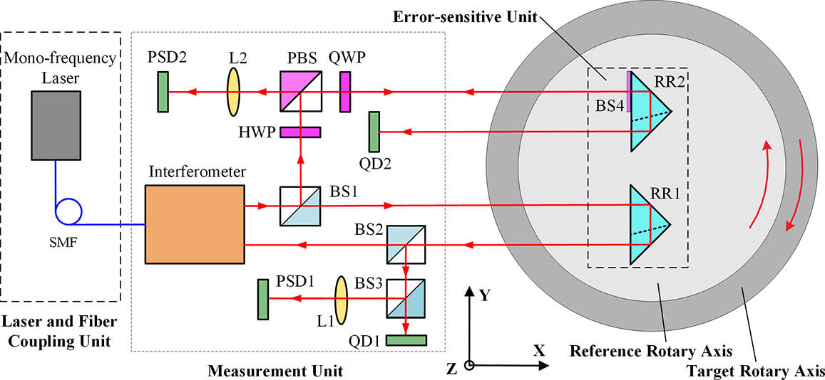
The schematic diagram of our method is shown in Fig. 1, which mainly includes the laser and fiber coupling unit, measurement unit, error-sensitive unit, and reference rotary axis. The reference rotary axis and the target rotary axis are coaxially mounted together, and the error-sensitive unit is fixed on the reference rotary axis. As the error-sensitive unit is composed of only two RRs, it has the advantages of small size, low weight, and no cable connection, which indicates that a high-precision and low-load rotary axis can be chosen as the reference rotary axis.
The laser beam transmits through a single-mode fiber (SMF) between the mono-frequency laser and the measurement unit. In this case, the heat generated by the laser can be isolated. Moreover, the spatial stability and energy distribution of the beam can be improved by the fiber. In the measurement unit, the beam is optically coupled into the miniature interferometer. The beam emitted from the interferometer is split by the beam splitter (BS1). The transmitted beam is reflected backward by the corner-cube RR1 in the error-sensitive unit and split by BS2. The beam transmitted through BS2 enters the interferometer. It is used as the measuring beam and interferes with the reference beam in the interferometer. The radial motion error around the axis will cause a change in the optical path of the measuring beam and can be measured by the interferometer. The beam reflected by BS2 is split by BS3. The transmitted beam enters the quadrant detector (QD1) to enable measurement of the radial motion errors along the axis and the axial motion error along the axis . The reflected beam is focused on PSD1 by the lens (L1) to monitor the beam drift in real time[19].
The beam reflected by BS1 is transmitted through the half-wave plate (HWP) and is reflected by the polarization BS (PBS). The reflected beam is transmitted through the quarter-wave plate (QWP) and enters RR2, whose semi-diameter is coated with a beam-splitting film (BS4) in the error-sensitive unit. The beam reflected by BS4 is transmitted through the QWP and PBS and is focused on PSD2 by L2 for enabling measurement of the angular positioning error and the tilt motion error around the axis .
The beam transmitted through BS4 is reflected backward by RR2 and detected by QD2. The tilt motion errors around the axis can be obtained from the results of QD1 and QD2.
Two key problems must be solved in order to simultaneously measure all six-DOF motion errors. First, the laser auto-collimation measurement system composed of BS4, L2, and PSD2 can only accurately measure a small angle. Its measuring range must be extended to 360°. Second, it must be ensured that the interferometric beam for measuring the radial motion error along the X axis is not interrupted. Only then can accurate counting of the interference fringes be ensured.
To solve these problems, the position of the light spot on PSD2 in the direction is used for the closed-loop control of the reference rotary axis. A fast and effective proportional-integral-derivative (PID) control algorithm was developed in addition to a data conversion and acquisition module with a field-programmable gate array as the core. When the target rotary axis rotates clockwise, the reference rotary axis will servo-track the target rotary axis and rotate anticlockwise. Thus, the light spot is always located in a limited area on the sensitive surface of PSD2, and the interferometric beam through BS2 is guaranteed to return to the interferometer throughout the measurement process. The schematic diagram of the PID closed-loop control is shown in Fig. 2. After analog-to-digital conversion and acquisition, the position information of the light spot on PSD2 is sent to the host computer through bluetooth. According to the input position information, the PID control algorithm will determine the parameters of the rotation angle and speed for servo tracking and send them to the driver and controller of the reference rotary axis.
Figure 2.Schematic diagram of the PID closed-loop control.
In this case, the angular positioning error can be expressed as where is the change in the position of the light spot on PSD2 in the direction, is the focal length of L2, and is the contra-rotation angle of the reference rotary axis.
To sum up, the corresponding photodetectors and expressions for each error are listed in Table 1, where is the distance between the two centers of the bottom surfaces of RR1 and RR2.
Motion Error
Detector
Expression
δx(θ)
Interferometer
Omitted
δy(θ)
QD1 or QD2
ΔYQD1/2 or ΔYQD2/2
δz(θ)
QD1 or QD2
ΔZQD1/2 or ΔZQD2/2
εx(θ)
QD1 and QD2
(ΔZQD1−ΔZQD2)/2h
εy(θ)
PSD2
ΔZPSD2/2f2
εz(θ)
PSD2
ΔYPSD2/2f2+θref−θ
Table 1. Corresponding Detectors and Expressions for Measuring Each DOF Motion Error of a Rotary Axis
According to the measurement principles mentioned above, we designed and built an experimental device for simultaneously and directly measuring all six-DOF motion errors of a rotary axis, mainly including a mono-frequency laser interferometer (SIOS, MI5000, resolution of 20 pm), a high-precision reference rotary axis (Aerotech, ANT95-360-R, accuracy of 10 arcsec, resolution of 0.01 arcsec, uni-directional repeatability of 0.5 arcsec), two QDs (Pacific Silicon Sensor, QP50-6SD2-DIAG, resolution of ), two PSDs (First Sensor, DL16-7-PCBA3, resolution of ), two RRs (Edmund, N-BK7, 3 arcsec beam deviation), and several other optical elements. As shown in Fig. 3, a CNC indexing table (KEOLEA, SKQ-200), which is one of the most important components of the CNC machine tools, was chosen as the target rotary axis. A photoelectric auto-collimator (Collapex EXP, accuracy of , resolution of ) was used for the comparison experiments of the tilt motion error around the axis and the angular positioning error. The distance between the measurement unit and the error-sensitive unit was 250 mm in the experimental device.
Considering the measurement resolution, accuracy, and range of the PSDs, and the compactness of the device[20], two compound lenses with a focal length of 200 mm were chosen as L1 and L2. According to the expressions in Table 1, the angular measurement resolution of the PSDs is 0.26 arcsec. As the resolution of the reference rotary axis is much higher, the resolution for measuring the angular positioning error and the tilt motion error around the axis can reach 0.26 arcsec. The distance is designed to be 30 mm so that the resolution for measuring the tilt motion error around the axis can reach 0.27 arcsec. According to the performance parameters of QDs, the resolution for measuring the radial motion error along the axis and the axial motion error along the axis can reach . The resolution for measuring the radial motion error along the axis is consistent with that of the interferometer, which is 20 pm. As listed in the second column of Table 2, the experimental device has relatively high resolutions for measuring each error and can satisfy most application requirements.
Errors
Resolution
SDS
MRV
δx(θ)
20 pm
0.03μm
3.9μm
δy(θ)
0.04μm
0.07μm
3.0μm
δz(θ)
0.04μm
0.04μm
0.7μm
εx(θ)
0.27 arcsec
0.05 arcsec
2.5 arcsec
εy(θ)
0.26 arcsec
0.17 arcsec
2.4 arcsec
εz(θ)
0.26 arcsec
0.06 arcsec
24.8 arcsec
Table 2. Measurement Resolution, Standard Deviation of Stability (SDS) and Maximum Repeatability Value (MRV)
We fixed the experimental device on an optical platform located on a concrete foundation for seismic isolation. The temperature of the laboratory was controlled at approximately . The calibration experiments were previously carried out[19]. A grating ruler (LG-50, accuracy of , resolution of ) was used to calibrate the straightness errors measured by QDs. In the range of , the linear-fit determination coefficient is up to 0.9996 and the standard deviation is . The photoelectric auto-collimator was used to calibrate the angular errors measured by PSDs. In the range of , the linear-fit determination coefficient is up to 0.9999 and the standard deviation is 0.58 arcsec.
The results of the stability experiment for 60 min are shown in the third column of Table 2. The maximum standard deviation of stability for measuring the straightness is for the radial motion error along the axis and that for measuring the angular errors is 0.17 arcsec for the tilt motion error around the axis. This demonstrated that our experimental device has good stability under the laboratory environment.
The results of measuring all six-DOF motion errors of the indexing table for five times are shown in Fig. 4. The solid lines marked with dots indicate the average of the experimental data. The dash lines marked with squares and triangles indicate the repeatability bands of the five measurements. The maximum repeatability values for each error are listed in Table 2. The maximum repeatability value is half of the maximum difference between the maximum and minimum of the five experiments at each measuring point. It can be observed that the maximum repeatability values for the other five-DOF motion errors except for the angular positioning error are small. We believe that this is due to the poor repeatability of the target rotary axis itself, which is validated by the following comparison experiments.
Figure 4.Results of the repeatability experiments for measuring all six-DOF motion errors of an indexing table.
A photoelectric auto-collimator was used for the comparison. Its sensitive unit (a plane mirror) was fixed on the back of the sensitive unit of our device. Thus, the tilt motion error around the axis and the angular positioning error of the target rotary axis can be measured by the two systems simultaneously. The results are shown in Fig. 5. The solid lines marked with dots indicate the average of the five measurements corresponding to the left coordinate axis. The dash lines marked with triangles indicate the deviations of comparison corresponding to the right coordinate axis. The maximum deviation of the comparison is 1.7 arcsec for the tilt motion error around the axis and 1.2 arcsec for the angular positioning error. The results demonstrated that our device has good consistency with the auto-collimator. However, certain deviations exist compared to the auto-collimator, which are mainly caused by error crosstalk, manufacturing errors, and so on. Further study will be done in the future.
Figure 5.Results of the comparison experiments between the auto-collimator and our device for measuring (a) the tilt motion error around the axis and (b) the angular positioning error.
The maximum deviation of the comparison for the angular positioning error is much smaller than that of repeatability, which confirms that the indexing table has poor repeatability for the angular positioning error.
Notably, the measurement process of our device has been automatized through closed-loop control and servo tracking, which can not only avoid the interference of human factors but also further improve the efficiency. Moreover, only one installation is required to measure all six-DOF motion errors. Therefore, it is believed that the influences of the changes in the environmental parameters such as the temperature and humidity and of the shift or deformation of the fixed components can be significantly reduced.
In conclusion, we have proposed a novel method for simultaneously and directly measuring all six-DOF motion errors of a rotary axis. Such a method is convenient to determine the error source and is capable of realizing online and in-process measurements. An experimental device was built, and a series of experiments was performed, including repeatability experiments and comparison experiments. The results demonstrate that all six-DOF motion errors of a rotary axis in the full-circle range can be simultaneously and directly measured by our method, which exhibits high resolution, good repeatability, and relatively high accuracy. By implementing closed-loop control and automatic measurement, both efficiency and accuracy are improved. By modeling and compensating the crosstalk errors between each other, the installation errors of the components, and the manufacturing errors of the optical elements, the measurement accuracy can be further improved. Owing to space limitation, the detailed models and compensating method will be given later.
Jiakun Li, Qibo Feng, Chuanchen Bao, Bin Zhang. Method for simultaneously and directly measuring all six-DOF motion errors of a rotary axis[J]. Chinese Optics Letters, 2019, 17(1): 011203