• High Power Laser Science and Engineering
  • Vol. 7, Issue 1, 010000e1 (2019)
D. Albach1、†,*, M. Loeser1, M. Siebold1, and U. Schramm1、2
Author Affiliations
  • 1Helmholtz–Zentrum Dresden–Rossendorf, Bautzner Landstraße 400, 01328 Dresden, Germany
  • 2Technische Universität Dresden, Zellescher Weg 19, 01069 Dresden, Germany
  • show less
    DOI: 10.1017/hpl.2018.59 Cite this Article Set citation alerts
    D. Albach, M. Loeser, M. Siebold, U. Schramm. Performance demonstration of the PEnELOPE main amplifier HEPA I using broadband nanosecond pulses[J]. High Power Laser Science and Engineering, 2019, 7(1): 010000e1 Copy Citation Text show less

    Abstract

    We report on the energetic and beam quality performance of the second to the last main amplifier section HEPA I of the PEnELOPE laser project. A polarization coupled double-12-pass scheme to verify the full amplification capacity of the last two amplifiers HEPA I and II was used. The small signal gain for a narrow-band continuous wave laser was 900 and 527 for a broadband nanosecond pulse, demonstrating 12.6 J of output pulse energy. Those pulses, being spectrally wide enough to support equivalent 150 fs long ultrashort pulses, are shown with an excellent spatial beam quality. A first active correction of the wavefront using a deformable mirror resulted in a Strehl ratio of 76% in the single-12-pass configuration for HEPA I.

    1 Introduction

    The fast evolution of high power laser systems in the peak power range of 100 terawatt (TW) to petawatt (PW)[1] has enabled and stimulated the field of relativistic plasma physics at peak intensities exceeding $10^{19}~\text{W}/\text{cm}^{2}$ and laser plasma based advanced particle accelerator concepts[2, 3]. For the particular application of compact laser ion accelerators, of potential interest for particle cancer therapy[4], not only peak power but also pulse energy matters[5]. Application orientation additionally requires a high average power of the laser system, i.e., pulse repetition rate.

    High-energy lasers using neodymium doped glass extend their capability toward shorter pulse duration and improved temporal pulse contrast necessary for such applications using optical parametric chirped-pulse amplification (OPCPA)[6, 7]. Lasers relying on titanium doped sapphire ($\text{Ti}^{3+}:\text{Al}_{2}\text{O}_{3}$/TiSa) currently demonstrate the highest peak power for pulses in the sub-50 fs range[5, 811]. However, all those systems rely on flash lamps to some extent and are thus limited in pulse repetition rate due to thermal load.

    With the increasing availability of laser diodes as optical pump sources, rare-earth-doped gain media became attractive for high average power laser systems up to the kW level[1216]. Most of these diode-pumped solid-state lasers (DPSSLs) operate with a pulse duration on the nanosecond time scale. Diode-pumped rare-earth-doped gain media show a significantly longer lifetime of the upper laser level compared to other gain media (e.g., TiSa); however they have to sacrifice on either bandwidth or gain cross section. There are only a few rare-earth-doped laser gain media capable of supporting ultrashort laser pulses in the 100 fs range on the one hand and being able to be scaled to the 100 J level and above on the other. Besides ytterbium doped glasses, ytterbium doped calcium fluoride ($\text{Yb}^{3+}$: $\text{CaF}_{2}$) is an interesting candidate[17, 18].

    Notably two fully, direct laser diode-pumped laser projects are located in Germany: the Polaris laser system in Jena relies on ytterbium doped glass and calcium fluoride $\text{Yb}^{3+}$: $\text{CaF}_{2}$[19, 20], while the PEnELOPE (Petawatt Energy Efficient Laser for Optical Plasma Experiments) laser project currently under development at the Helmholtz–Zentrum Dresden–Rossendorf uses the latter material alone[21].

    The PEnELOPE laser aims at 150 fs, 150 J on target. A repetition rate of up to 1 Hz becomes feasible by utilization of a proven high pressure helium gas-cooled multi-slab amplifier head design[15, 16]. In order to achieve these parameters, challenges lie mainly in the pulse amplification to the desired energy level, as well as the successful stretching and compression of those ultrashort laser pulses. With these pulse parameters, laser ion acceleration experiments with expected proton energies in the 100 MeV range are envisioned. In this paper we detail the efforts to verify the amplification capacity of the amplifier design chosen for the high-energy power amplifier stages of PEnELOPE.

    2 Setup description

    Figure 1 shows the principle setup of the PEnELOPE laser system. A commercial oscillator (Flint, Light Conversion) generates 65 fs long pulses at a repetition rate of 78 MHz and a pulse energy of about 10 nJ with the central wavelength at 1035 nm. Pulse picking down to 1 Hz and stretching to 10 ns hard clip (4.4 ns full width at half-maximum (FWHM)) is performed before entering a first set of amplifiers with a stretching factor of 200 ps/nm and a 50 nm hard clip[21].

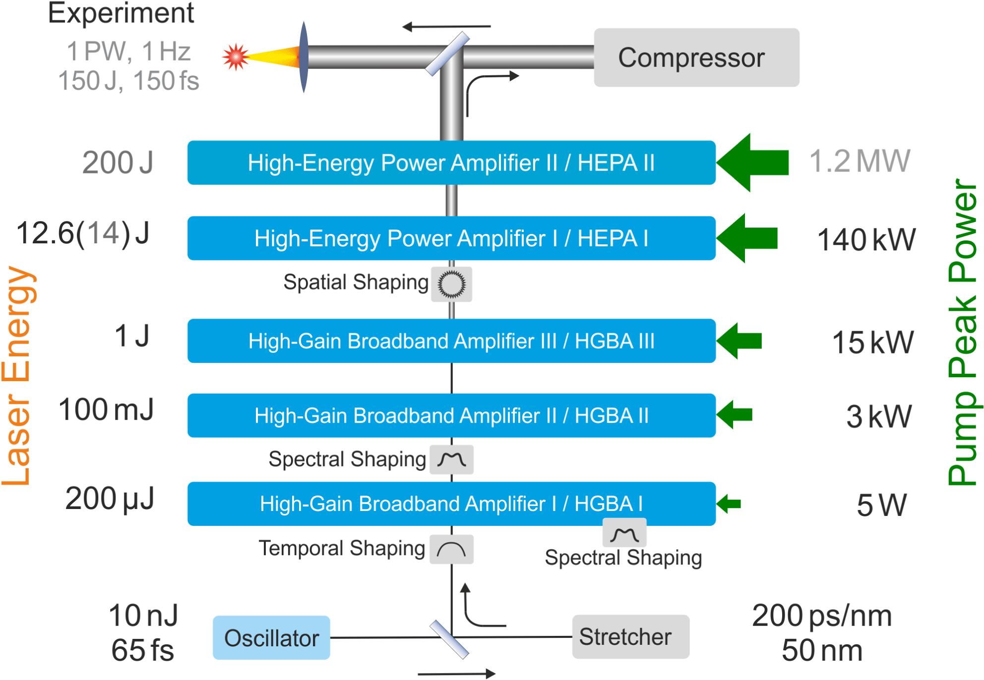
    The initial set of amplifiers boosts the energy from the nanojoule to the joule level and therefore does the highest amount of work in terms of energetic gain, while the initial spectral bandwidth should be preserved. They are consequently named high-gain broadband amplifiers (HGBAs).

    With $\text{Yb}^{3+}$: $\text{CaF}_{2}$ having roughly the same amplification bandwidth compared to the initial spectral bandwidth of the stretched pulse (in the order of 20 nm), one can estimate the gain narrowing factor $\unicode[STIX]{x1D705}$ to be $\unicode[STIX]{x1D705}\approx (\ln G_{0}+1)^{1/2}$ with $G_{0}$ the total gain[22]. With HGBA I amplifying the pulse energy by $10^{4}$$10^{5}$, one can expect $\unicode[STIX]{x1D705}$ between 3.2 and 3.5, consequently reducing the bandwidth of a typical $\text{Yb}^{3+}$: $\text{CaF}_{2}$ regenerative amplifier to about 6 nm. Therefore, the amplification scheme relies on spectral gain shaping, either intra-cavity (regenerative amplifier HGBA I) or prior to injection into the following linear amplifier section (i.e., before HGBA II).

    Unfortunately, $\text{Yb}^{3+}$: $\text{CaF}_{2}$ absorption and emission cross sections[23] imply a high number of extraction passes for the linear amplification stages HGBA II and III. A typical gain per pass is in the order of 1.3 resulting in at least 10 passes for an amplification factor of 10. Amplifier HGBA II is designed for 16 and HGBA III 12 passes to accommodate for their respective gain.

    The second amplifier section consists of two high-energy power amplifiers (HEPA I and II). Despite the majority of the gain performed already, the lion’s share of the diode pump power, thus the related thermal management, concentrates in those instruments. Consequently it is crucial to thoroughly design and test the average power capacity of those amplifiers after the initial confirmation of energetic amplification capacity.

    With that many passes through a large size, high-energy amplifier a fully imaged setup is preferable, as free propagation would lead to a significant loss in spatial beam quality due to static and pump induced wavefront aberration. As long as the main source of wave front error lies in (or sufficiently close to) the respective image planes, a careful placement of a correction system (either static or adaptive) can eliminate most of the aberration impact without sacrificing spatial beam quality too much. The correction should be as close as possible to the origin of the major wavefront aberration. Otherwise, one would need at least two deformable mirrors to correct near- and far-field independently[24, 25]. For PEnELOPE the wavefront correction positions are foreseen to be positioned in the image planes of HEPA I and II, as well as at the exit of the compressor.

    As highest extraction efficiency is desired, a flat top pump and extraction profile yields the best results, while minimizing laser induced damage issues. In order to optimize beam quality and to mitigate laser induced damage, a fully imaged amplifier setup was chosen for both amplifiers HEPA I and II with an emphasis on a minimal free propagation distance between the optical elements for each of its passes.

    The general setup of HEPA I is shown in Figure 2. It uses 12 passes through a high pressure gas-cooled amplifier head consisting of four 5 mm thick and 55 mm diameter slabs and suitable high pressure windows[15, 16]. The doping concentration was set to commercially available 1.9 at.%, which allows for about 95% of absorption of the 940 nm laser diode emission in a double-pass pump scheme[21]. This double-pass scheme is necessary due to the high pump saturation intensity of about $55~\text{kW}/\text{cm}^{2}$ at 940 nm[18] and consequently to keep a manageable doping concentration for a given thickness[26]. It opens the path to a higher excitation ratio of the ytterbium doped material, but requires a more strict imaging and beam shaping approach for the pump. For this reason we designed a fully imaged pump system with up to 70 kW of peak power per side with a brightness of $1.7~\text{MW}/(\text{sr}\cdot \text{cm}^{2})$. This enables us to use an angular multiplexed double-pass setup for HEPA I with pump intensities up to $16.5~\text{kW}/\text{cm}^{2}$.

    Estimating the amplified spontaneous emission (ASE) impact on the energy storage capacity was performed by HASEonGPU[27]. In our case of a characteristic value of $g_{0}L<2$, we find a very low impact of ASE on the stored energy density[28]. This results in return in our geometry, as mentioned before, in a low small signal gain (SSG) of about 1.3 per pass in transmission through four slabs. In our numerical modeling the uncertainty of the expected life time, absolute values of cross sections and spectral distribution of both pump and extraction far exceed the ASE impact. Nevertheless, with increasing pump intensity and pump duration, ASE reduces further the energy storage capacity and consequently the SSG. Those changes, being in the order of about 1%, are only measurable in a multi-pass setup.

    To avoid chromatic aberration and ghost reflection as far as possible and to increase the compactness of the system, a fully reflective setup was chosen using telecentric telescopes. In order to avoid breakdown close to the foci, the telescopes are under vacuum. The spherical mirrors have focal lengths of 1 m and 1.35 m (magnification 1.35) to reduce the average energy density, especially after the last amplification pass and the following transport optics at the same time. The overall challenge in constructing such a setup lies in reducing the losses due to the finite reflectivity, notably for the laser gain medium slabs.

    The full setup of HEPA I was modeled with Zemax. Considering perfect surfaces and transmission optics (gain media slabs, windows), one can achieve a Strehl ratio (SR) of more than 95% in 12 passes, as shown in Figure 3(a). Replacing the doped gain medium slabs with similar coated fused silica slabs results in an SR of 75% (see Figure 3(b)).

    Primary ghost reflections, especially from the slabs, were suppressed by applying a wedge and blocking those unwanted reflections by reasonably sized pinholes close to the focal planes of the individual telescopes.

    In the case of the 12 passes in HEPA I, we found a total transmission of 95% in the experiment, when the doped gain medium is replaced with similar coated fused silica slabs, and 15% transmission inserting the $4~\text{Yb}^{3+}$: $\text{CaF}_{2}$ slabs, doped at 1.9 at.% each. Combining HEPA I and II together, a B-integral of less than 0.5 rad is estimated for the final system design, a relatively small number considering the large amount of passes through each amplifier section, only possible using fully reflective transport optics.

    Amplifier stage HEPA II is designed in a similar fashion as HEPA I, but scaled to the 200 J level. The pump peak power is 1.2 MW at 976 nm with an increased brightness of the laser diode pump source to more than $2.5~\text{MW}/(\text{sr}\cdot \text{cm}^{2})$ to further facilitate pump beam shaping and transport. The laser slab diameter is increased from 55 mm to 110 mm, with the extraction beam diameter being 80 mm instead of 25 mm.

    In order to experimentally prove the SSG capacity of the combined setup of HEPA I and II on the one hand and to show the energetic and spectral capacity on the other, a double pass through HEPA I using polarization coupling was set up. Now, instead of the originally intended 12 passes, 24 passes are implemented, effectively simulating both amplifiers in terms of total gain and spectral gain narrowing impact using HEPA I alone.

    However, during testing the high pressure windows, an excessive amount of birefringence was found. In order to perform the polarization coupling, the high pressure windows had to be removed from the assembly, leaving the laser slabs to the same condition as the remaining amplifier section (i.e., under vacuum as the telescopes or under ambient air) and restricting the operation to single shot only.

    3 Experimental results

    In order to assess the performance of this double-pass configuration, we opted for three performance tests. The first was the probing of the SSG using a continuous wave (cw) laser, where the whole setup was left under ambient condition. The second step was the energetic activation of the amplifier with an additional emphasis on the reproduction of the SSG experiments on the one hand and to gain insight into the spectral behavior of the whole setup on the other. We investigated the spectral performance of the entire amplifier chain to support sub-150 fs pulses. This step at high pulse energies had to be performed under vacuum, where due to the absence of the high pressure windows also the amplifier operated under vacuum condition. The last step was the observation of the near- and far-field quality, which is an important feature for the reliable pulse compression and beam transport into the envisioned target area.

    3.1 Small signal gain probing

    With an SSG of about 1.3 per pass only, one can expect a total SSG of 543 in 24 passes, while 1.31 will ultimately result in an SSG of 652. Both results are easily distinguishable and therefore we can measure the SSG per pass with a precision otherwise not accessible in a single pass regime.

    We injected a narrow-band cw source at 1030.0 nm with a beam diameter of 2 mm, effectively probing the gain medium at the center only. The pump light distribution is homogeneous (less than 2% rms, see the inset in Figure 2) within a propagation of 30 mm out of focal plane. We are therefore sure to excite the pumped volume spatially uniform.

    As we used the setup in 24 passes, only 2.2% transmission was found, which matches very well the expected absorption for the ytterbium doped slabs at ambient temperature. Figure 4(a) shows the SSG for different pump durations as a function of the average pump intensity on a logarithmic scale. One has to note, that the measured SSG stretches over almost five orders of magnitude. Such a measurement is only possible using finely calibrated neutral density filters. The setup is similar to the one in Ref. [29]. With the available pump power and duration of up to 4 ms, a maximum SSG of 900 was found.

    For a short pump duration (i.e., ${<}$1 ms) no effective positive gain is found and therefore the graph shows a perfect exponential behavior (linear on a logarithmic scale). For longer pump durations an onset of saturation is found. This can be attributed to the onset of pump saturation and the impact of ASE, despite the gain per pass being very low (${<}$1.33 per pass).

    Thermal roll-over (TRO) can be ruled out, as for this particular setup the whole laser was under normal pressure. It was not necessary to put in the vicinity of the foci under vacuum, as only a cw laser was used. Consequently all four slabs were air cooled during the individual single shots with about one shot per 5 min. Reference shots were taken at the beginning and the end of the individual shot series that showed no sign of thermal impact on the SSG.

    As already mentioned, about 1 ms of pump duration is needed to surpass an SSG of 1, even at the highest available pump intensity. This indicates that in our case with a maximum pump duration of 4 ms, a significant amount of pump energy is lost due to the ground state absorption, which is a common drawback of any ytterbium doped gain medium at room temperature.

    To mitigate this issue we plan to use the amplifiers at a lower temperature in the future, notably in the 200 K to 250 K range to reduce the reabsorption and harness the improved thermo-mechanical properties at the same time. Keeping the operation in this range, spectral modulations are still negligible, which appear at even lower temperatures[23, 30].

    3.2 Energy extraction using nanosecond pulses

    With the SSG for a narrow-band cw laser far exceeding the needed factor of 200, one can go forward to estimate the gain performance for a broader spectrum, much closer to the spectral distribution out of HGBA III.

    In order to assess the scaling of the spectral bandwidth behavior of the large amplifier setup and in order to verify the results obtained using the narrow-band laser, we opted for a broadband, nanosecond cavity-dumped oscillator with 6 ns (FWHM) long pulses as a seed source for HGBA II instead of the chirped-pulse amplification (CPA) oscillator together with its front end. Using this approach we avoid the danger to generate a short pulse by narrowing the spectrum, as it would happen in a stretched CPA pulse due to the spectral–temporal coupling.

    By adapting the regenerative amplifier HGBA I to its cavity-dumped mode, we have an easy way to manipulate the bandwidth without changing the temporal width of the pulse. We used the aforementioned output of HGBA II and varied the energy input into the double-12-pass HEPA I setup by the means of a half-wave plate and a polarizer.

    In order to verify the SSG results obtained by a cw laser at 1030 nm, a narrow-band input of 0.7 nm FWHM (case A) was prepared. The 5 nm FWHM bandwidth case (case B) corresponds to the natural spectral behavior of an ytterbium doped CaF$_{2}$ amplifier working at room temperature, while the broadband case (case C) with its 16 nm at FWHM mimics a typical spectral distribution used as a seed for the envisioned pulse duration of 150 fs FWHM.

    At this point we have to point out, that the whole setup was under vacuum condition, including the amplifier head with the four gain medium slabs. As it was mentioned before, the high pressure windows showed too much birefringence that did not allow using any polarization coupling and were therefore omitted.

    Figure 4(b) shows the output energy as a function of the input energy of the setup for the three different input spectral cases A, B and C. The corresponding gain is given for each curve. Taking a look on the narrow-band case (A), one can expect to find, for very low input energies, a gain very similar to the SSG of 900 out of Figure 4(a). Indeed, the measured gain of 890 corresponds sufficiently well to the measured SSG of 900 within the accuracy of the setup.

    The gain drops at an output energy of 10 J from 820 to 610 by increasing the input spectral width from 0.7 nm (case A) to 5 nm (case B) and again to 444 with 16 nm (case C) at the input, when interpolating the spline fit.

    As mentioned earlier, for this setup the gain medium slabs were under vacuum in contrast to the SSG experiments discussed before. This leads to the inevitable buildup of heat, resulting in a slight reduction of the gain per pass with an increasing number of successive shots. Considering 24 passes, this leads to a rather significant impact on the gain curve in the form of a TRO, even when working in a single-shot regime.

    Between individual following shots (more than 5 min between each shot) no thermal effect was directly visible. However, over the course of a day a deviation from the expected behavior was found (TRO was visible). A separate shot on the next day revealed the full energetic performance for the cases B and C eliminating the TRO. An energy of 12.6 J was found in both cases.

    Figure 5(a) shows the spectra of HGBA II for three different spectral settings that acted as the energy extraction cases. The spectra were measured with a relative intensity calibrated spectrometer (AVASPEC-UL2048CL-Evo, Avantes). Figure 5(b) shows the spectra at the output of the double-12-pass setup for the corresponding energy shots.

    The most narrow-band case (A) stays virtually the same, as one can expect from the rather broadband nature of the gain medium. The intermediate case (B) behaves as expected with only a minor bandwidth reduction and a slight shift toward longer wavelengths.

    The most broadband case (C) however shows the expected gain narrowing between 1030 nm and 1035 nm. A Fourier transform of the amplified spectrum reveals 146 fs for this first try, proving the bandwidth capacity of the whole amplifier setup and spectral shaping strategy of PEnELOPE. Figure 6(a) shows the beam profile for case C (16 nm FWHM) with an output energy of 12.6 J. If one would assume a perfect flat top beam and a perfect fit to the 25 mm beam diameter (33.8 mm after magnification by 1:1.35), one could estimate a pulse energy of more than 30 J.

    3.3 Near- and far-field observation

    Despite that the setup of HEPA I was initially not designed to support a double-12-pass amplification scheme, the near-field image quality could be sustained. Taking a look into the beam profile in Figure 6(a), one can clearly observe a slight asymmetry, which is due to the imperfect last 12 of the overall 24 passes. Another distinctive feature is the high spatial frequencies which are due to the crystal quality of the laser gain medium. Still, the spatial beam quality is excellent, exceeding typical beam profiles under free propagation[20].

    The far-field quality of such laser pulses is of utmost importance to reach highest in-focus intensities, with the Fourier limit as its target. We concentrated on three different aspects. At first we wanted to assess the laser amplifier design in terms of far-field quality, second the energy extraction setup including gain medium and transport optics without any far-field correction applied. As a last point we wanted to explore the future potential of a wavefront correction to achieve a focal spot as close as possible to the Fourier limit in the initially designed 12-pass setup, as HEPA I and II have individual deformable mirror systems.

    As mentioned before, the laser amplifier simulation using Zemax indicated for HEPA I a limiting SR close to 95%, omitting the individual mirror and gain medium quality. Nevertheless, any random nonrotational symmetric wavefront error from the optics outside the image planes of the single-12-pass setup statistically balances each other. Optics situated in the individual image planes is hit under each pass respectively, which in return will generate the majority of the accumulated wavefront error. After 12 passes we measured an SR of 75% using the wavefront sensor with the laser gain medium replaced by fused silica slabs. We have to consider about $\unicode[STIX]{x1D706}$/10 wavefront error of the used mirrors in the image plane. The majority of the wavefront error is fortunately a focus/defocus component typically, which is easily compensated by fine tuning the distance between the spherical mirrors in our setup. With 24 passes we measured an SR of 31%, which is expected, as the square of the rms wavefront error adds up[31]. In order to reduce the wavefront error of the entire system even further, a correcting element would be necessary (static or active).

    The next step was to exchange the fused silica slabs with the doped gain medium slabs. Measuring those slabs using a Fizeau interferometer (Accufiz, 4DTechnology), we can estimate a wavefront error per pass of about 0.2$\unicode[STIX]{x1D706}$ by those four slabs together. In order to realize the energetic extraction, the full polarization coupling, including all the transport optics, was measured together with HEPA I in order to realize the double-12-passes.

    For this particular setup we decided to measure the near-field by imaging the near beam profile of a 1064 nm cw laser onto a camera (SP620U, Spiricon). Taking advantage of the focal spot of the first lens in the image relaying telescope, the far-field was measured directly. Out of the near-field we calculated the corresponding far-field with a perfectly flat wavefront. Dividing the measured intensity by the calculated ideal one yields by definition the SR[31, 32]. Using the cw laser at 1064 nm we can investigate the full far-field potential of the amplifier setup as the wavefront can be prepared to an almost perfect flat one and we do not have to rely on the far-field quality of the intermediate HGBA I in its cavity-dumped mode.

    The measured far-field is shown in Figure 7(a). Despite the beam in the far-field is only 2.5 and 1.4 times the Fourier limit (FWHM), only an SR of 12% is found. This is a good example that one cannot rely on the central lobe alone[33] (in this example it contains about 25% of the total energy). Taking a similar picture using the initially designed 12 passes we find about 24% for the SR in Figure 7(b). It is obvious, that a wavefront correction is necessary. A first implementation of a deformable mirror (DM50-32, AKA Optics) corrected the wavefront in our initially designed single-12-pass for HEPA I to an SR of about 76% including all the transport optics.

    Figure 7(c) shows clearly, that the wavefront can be sustained in the transport through HEPA I and all the optics including the transport into the next amplifier section HEPA II. Section HEPA II will receive its own set of adaptive optics in its entrance image plane to correct for the amplifier and the transport into the compressor. After compression, a final deformable mirror will correct for the transport into the target area and onto the target.

    4 Conclusion

    We installed and successfully used the fully imaged and reflective second to the last amplifier section HEPA I to amplify broadband nanosecond pulses. In order to prove the energetic and spectral performance of both last amplifier sections relying on $\text{Yb}^{3+}$: $\text{CaF}_{2}$ together, HEPA I and II, a double-12-pass extraction setup through HEPA I using polarization coupling was used.

    With an SSG of 900 and the measured energetic gain of more than 500 for broadband nanosecond pulses at room temperature under single-shot condition we far exceeded the necessary gain of 200 with enough margin considering the envisioned case of a sub-room temperature operation of the amplifier head.

    In our experimental campaign we achieved a pulse energy of 12.6 J using broadband nanosecond pulses out of the front end amplifier section. CPA pulses with a similar spectrum would show a Fourier limit below 150 fs without any further spectral shaping campaign necessary.

    Small scale near-field spatial modulations result from imperfections of the gain medium, while at the same time the very first iteration of a far-field optimization shows a measured SR of 76% under 12 passes. Together with the relatively smooth near-field output beam profile this is to our knowledge the best beam quality for multi-pass 10 J scale amplifiers relying on $\text{Yb}^{3+}$: $\text{CaF}_{2}$ demonstrated to this date. Together with the installation of a deformable mirror system within the last amplifier section HEPA II and after compression we are sure to maintain this performance down to the laser target area for even higher energies.

    With this benchmark of HEPA I we are therefore confident to ultimately deliver ultrashort high quality laser pulses on the 150 J level with good spectral properties and the desired high quality in near- and far-field to the target area with the upcoming activation of the last amplifier section HEPA II for future laser particle acceleration campaigns.

    References

    [1] C. Danson, D. Hillier, N. Hopps, D. Neely. High Power Laser Sci. Eng., 3, e3(2015).

    [2] C. Downer, R. Zgadzaj, A. Debus, U. Schramm, M. Kaluza. Rev. Mod. Phys., 90(2018).

    [3] A. Macchi, M. Borghesi, M. Passoni. Rev. Mod. Phys., 85, 751(2013).

    [4] U. Masood, T. E. Cowan, W. Enghardt, K. M. Hofmann, L. Karsch, F. Kroll, U. Schramm, J. J. Wilkens, J. Pawelke. Phys. Med. Biol., 62, 5531(2017).

    [5] U. Schramm, M. Bussmann, A. Irman, M. Siebold, K. Zeil, D. Albach, C. Bernert, S. Bock, F. Brack, J. Branco, J. P. Couperus, T. E. Cowan, A. Debus, C. Eisenmann, M. Garten, R. Gebhardt, S. Grams, U. Helbig, A. Huebl, T. Kluge, A. Köhler, J. M. Krämer, S. Kraft, F. Kroll, M. Kuntzsch, U. Lehnert, M. Loeser, J. Metzkes, P. Michel, L. Obst, R. Pausch, M. Rehwald, R. Sauerbrey, H.–P. Schlenvoigt, K. Steiniger, O. Zarini. J. Phys. Conf. Ser., 874(2017).

    [6] E. W. Gaul, M. Martinez, J. Blakeney, A. Jochmann, M. Ringuette, D. Hammond, T. Borger, R. Escamilla, S. Douglas, W. Henderson, G. Dyer, A. Erlandson, R. Cross, J. Caird, C. Ebbers, T. Ditmire. Appl. Opt., 49, 1676(2010).

    [7] N. Miyanaga, H. Azechi, K. A. Tanaka, T. Kanabe, T. Jitsuno, J. Kawanaka, Y. Fujimoto, R. Kodama, H. Shiraga, K. Knodo, K. Tsubakimoto, H. Habara, J. Lu, G. Xu, N. Morio, S. Matsuo, E. Miyaji, Y. Kawakami, Y. Izawa, K. Mima. J. Phys. IV, 133, 81(2006).

    [8] H. Kiriyama, M. Mori, A. S. Pirozhkov, K. Ogura, A. Sagisaka, A. Kon, T. Zh Esirkepov, Y. Hayashi, H. Kotaki, M. Kanasaki, H. Sakaki, Y. Fukuda, J. Koga, M. Nishiuchi, M. Kando, S. V. Bulanov, K. Kondo, P. R. Bolton, O. Slezák, D. Vojna, M. Sawicka-Chyla, V. Jambunathan, A. Lucianetti, T. Mocek. IEEE J. Sel. Top. Quantum Electron., 21, 232(2015).

    [9] X. Zeng, K. Zhou, Y. Zuo, Q. Zhu, J. Su, X. Wang, X. Wang, X. Huang, X. Jiang, D. Jiang, Y. Guo, N. Xie, S. Zhou, Z. Wu, J. Mu, H. Peng, F. Jing. Opt. Lett., 42, 2014(2017).

    [10] J. H. Sung, H. W. Lee, J. Y. Yoo, J. W. Yoon, C. W. Lee, J. M. Yang, Y. J. Son, Y. H. Jang, S. K. Lee, C. H. Nam. Opt. Lett., 42, 2058(2017).

    [11] K. Nakamura, H.-S. Mao, A. J. Gonsalves, H. Vincenti, D. E. Mittelberger, J. Daniels, A. Magana, C. Toth, W. P. Leemans. IEEE J. Quantum Electron., 53, 121(2017).

    [12] A. Bayramian, J. Armstrong, G. Beer, R. Campbell, B. Chai, R. Cross, A. Erlandson, Y. Fei, B. Freitas, R. Kent, J. Menapace, W. Molander, K. Schaffers, C. Siders, S. Sutton, J. Tassano, S. Telford, C. Ebbers, J. Caird, C. Barty. J. Opt. Soc. Am. B, 25, B57(2008).

    [13] R. Yasuhara, T. Kawashima, T. Sekine, T. Kurita, T. Ikegawa, O. Matsumoto, M. Miyamoto, H. Kan, H. Yoshida, J. Kawanaka, M. Nakatsuka, N. Miyanaga, Y. Izawa, T. Kanabe. Opt. Lett., 33, 1711(2008).

    [14] T. Goncalves-Novo, D. Albach, B. Vincent, M. Arzakantsyan, J.-C. Chanteloup. Opt. Express, 21, 855(2013).

    [15] S. Banerjee, K. Ertel, P. D. Mason, P. J. Phillips, M. De Vido, J. M. Smith, T. J. Butcher, C. Hernandez-Gomez, R. J. S. Greenhalgh, J. L. Collier. Opt. Express, 23, 19542(2015).

    [16] O. Novák, T. Miura, M. Smrž, M. Chyla, S. Nagisetty, J. Mužík, J. Linnemann, H. Turčičová, V. Jambunathan, O. Slezák, M. Sawicka-Chyla, J. Pilař, S. Bonora, M. Divoký, J. Měsíček, A. Pranovich, P. Sikocinski, J. Huynh, P. Severová, P. Navrátil, D. Vojna, L. Horáčková, K. Mann, A. Lucianetti, A. Endo, D. Rostohar, T. Mocek. Appl. Sci., 5, 637(2015).

    [17] V. Petit, J.L. Doualan, P. Camy, V. Ménard, R. Moncorgé. Appl. Phys. B, 78, 681(2004).

    [18] M. Siebold, S. Bock, U. Schramm, B. Xu, J. L. Doualan, P. Camy, R. Moncorgé. Appl. Phys. B, 97, 327(2009).

    [19] J. Hein, M. C. Kaluza, R. Bödefeld, M. Siebold, S. Podleska, R. Sauerbrey. Lect. Notes Phys., 694, 47(2006).

    [20] M. Hornung, H. Liebetrau, S. Keppler, A. Kessler, M. Hellwing, F. Schorcht, G. A. Becker, M. Reuter, J. Polz, J. Körner, J. Hein, M. C. Kaluza. Opt. Lett., 41, 5413(2016).

    [21] M. Siebold, F. Roeser, M. Loeser, D. Albach, U. Schramm. Proc. SPIE, 8780(2013).

    [22] I. N. Ross, M. Trentelman, C. N. Danson. Appl. Opt., 36, 9348(1997).

    [23] J. Koerner, C. Vorholt, H. Liebetrau, M. Kahle, D. Kloepfel, R. Seifert, J. Hein, M. C. Kaluza. J. Opt. Soc. Am. B, 29, 2493(2012).

    [24] H. Baumhacker, G. Pretzler, K. J. Witte, M. Hegelich, M. Kaluza, S. Karsch, A. Kudryashov, V. Samarkin, A. Roukossouev. Opt. Lett., 27, 1570(2002).

    [25] J. D. Barchers. J. Opt. Soc. Am. A, 19, 926(2002).

    [26] M. Siebold, M. Loeser, U. Schramm, J. Koerner, M. Wolf, M. Hellwing, J. Hein, K. Ertel. Opt. Express, 17, 19887(2009).

    [27] C. H. J. Eckert, E. Zenker, M. Bussmann, D. Albach. Comput. Phys. Commun., 207, 362(2016).

    [28] C. Orth, S. Payne, W. Krupke. Nucl. Fusion, 36, 75(1996).

    [29] D. Albach, J.-C. Chanteloup, G. le Touzé. Opt. Express, 17, 3792(2009).

    [30] J. Körner, V. Jambunathan, J. Hein, R. Seifert, M. Loeser, M. Siebold, U. Schramm, P. Sikocinski, A. Lucianetti, T. Mocek, M. C. Kaluza. Appl. Phys. B, 116, 75(2014).

    [31] V. N. Mahajan. J. Opt. Soc. Am., 72, 1258(1982).

    [32] A. S. Pirozhkov, Y. Fukuda, M. Nishiuchi, H. Kiriyama, A. Sagisaka, K. Ogura, M. Mori, M. Kishimoto, H. Sakaki, N. P. Dover, K. Kondo, N. Nakanii, K. Huang, M. Kanasaki, K. Kondo, M. Kando. Opt. Express, 25, 20486(2017).

    [33] P. Mason, M. Divoký, K. Ertel, J. Pilař, T. Butcher, M. Hanuš, S. Banerjee, J. Phillips, J. Smith, M. De Vido, A. Lucianetti, C. Hernandez-Gomez, C. Edwards, T. Mocek, J. Collier. Optica, 4, 438(2017).

    D. Albach, M. Loeser, M. Siebold, U. Schramm. Performance demonstration of the PEnELOPE main amplifier HEPA I using broadband nanosecond pulses[J]. High Power Laser Science and Engineering, 2019, 7(1): 010000e1
    Download Citation