
Yi Xiao, Ya Bai, Peng Liu. Single-Shot Time-domain Spectrum Detection for Terahertz Radiation[J]. Chinese Journal of Lasers, 2019, 46(6): 0614009
- Chinese Journal of Lasers
- Vol. 46, Issue 6, 0614009 (2019)
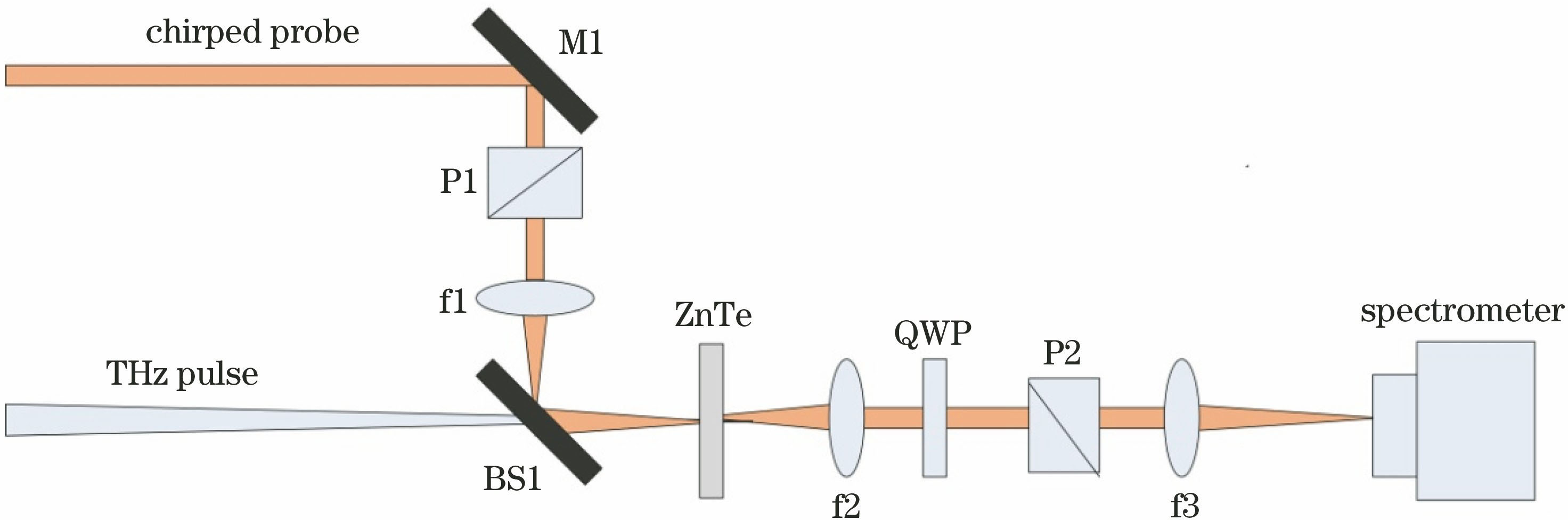
Fig. 1. Experimental setup of spectrum detection with chirped pulse
![Experimental results[11-12]. (a) Time-domain waveform obtained by conventional THz measurement based on pump-probe technique; (b) time-domain waveform based on spectrum detection with chirped pulse; (c)frequency spectrum obtained by conventional THz measurement based on pump-probe technique; (d) frequency spectrum based on spectrum detection with chirped pulse](/richHtml/zgjg/2019/46/6/0614009/img_2.jpg)
Fig. 2. Experimental results[11-12]. (a) Time-domain waveform obtained by conventional THz measurement based on pump-probe technique; (b) time-domain waveform based on spectrum detection with chirped pulse; (c)frequency spectrum obtained by conventional THz measurement based on pump-probe technique; (d) frequency spectrum based on spectrum detection with chirped pulse
Fig. 3. Experimental setup of spectral interference detection with chirped pulse
Fig. 4. Simulated results. (a) Simulated spectral interference fringes with THz field; (b) corresponding time-domain results with THz field; (c) simulated spectral interference fringes without THz field; (d) corresponding time-domain results without THz field
Fig. 5. Time-domain waveforms obtained by spectral interferometry with chirped pulse[15]. (a) THz spatiotemporal waveform extracted from interference fringe; (b) waveform when y=0 mm
Fig. 6. Diagrams of experimental setup[16]. (a) Experimental setup of non-common-path spectral interference; (b) experimental setup of common-path spectral interference
Fig. 7. THz time-domain waveforms obtained by two pumping methods[16]
Fig. 8. Experimental setup of improved common-path spectral interference[17]
Fig. 9. Experimental setup of space-time encoding detection
Fig. 10. THz time-domain waveforms obtained by space-time encoding detection[28] (the top line is the result of single-shot measurement, the bottom dotted line is the result of averaging single-shot data, and the solid line is the result of traditional method based on pump-probe technique)
Fig. 11. Principle of single-shot measurement using pulse-front tilting method[30]
Fig. 12. Time-domain waveform of THz pulse measured by using pulse-front tilting method with prism[30]
Fig. 13. Experimental setup of space-time encoding detection with second harmonic
Fig. 14. THz time-domain waveform obtained by second-harmonic cross-correlation method[29]
Fig. 15. Principle diagram of dual echelons[32]
Fig. 16. Experimental setup of single-shot detection using dual echelons
Fig. 17. Experimental results of dual echelons (top) and traditional method based on pump-probe detection technique (bottom)[32]
Fig. 18. Schematic of single-echelon technique[33]
Fig. 19. Schematic of reflective dual echelons[34]
Fig. 20. Measurement principle of THz streak camera[36]
|
Table 1. Comparison of parameters[9]


Set citation alerts for the article
Please enter your email address

© Copyright 2018-2021 | Chinese Laser Press. All Rights Reserved 沪ICP备15018463号-20