
Zhixian Li, Min Fu, Xiaofan Zhao, Hongye Li, Zilun Chen, Zefeng Wang, Jinbao Chen, "Fabrication of side pump combiners when pumping with a laser diode and a fiber laser," Chin. Opt. Lett. 20, 021401 (2022)
- Chinese Optics Letters
- Vol. 20, Issue 2, 021401 (2022)
Abstract
1. Introduction
Fiber laser sources have attracted more and more attention due to their high conversion efficiency, good beam quality, compact structure, and convenient thermal management[
Side pumping technology can be divided into non-all-fiber pumping technology and all-fiber pumping technology. Non-full fiber side pumping technology is usually achieved with the help of complex optical devices such as adhesive microprisms[
Among the all-fiber structure of the side pump technology, the combiner fabricated with taper-fused method is considered to be the key element to realize the high-power fiber laser due to the high efficiency, high-power processing capability, and low signal loss. The side pumping combiner based on the taper-fused method was reported in previous research for both LD pumping and YDFL tandem pumping structures. For the LD pumping scheme, in 2012, Theeg et al. reported a
Sign up for Chinese Optics Letters TOC. Get the latest issue of Chinese Optics Letters delivered right to you!Sign up now
In this study, for the first time, to the best of our knowledge, we have separately studied the different manufacturing parameters of the side pumped combiner catering for LD pumping and high-brightness YDFL pumping. Theoretically, the geometrical optics theory was used to analyze the propagation path of pump light with different numerical apertures (NA) in the side pump combiner, which provides a useful reference for the manufacturing process. Experimentally, we have studied the pump coupling efficiency and temperature characteristics of the side pump combiner when it was pumped by an LD and a YDFL. By changing the fusion area between the signal fiber and the tapered pump fiber, a side pump combiner with high coupling efficiency can be manufactured in the case of LD pumping and YDFL pumping, respectively. In the LD pumping case, the maximum coupled pump power from one pump port was 1200 W with the coupling efficiency of 97%, and the highest temperature rise coefficient of the combiner was 12.41°C/kW. In the YDFL pumping case, the maximum coupled pump power from one pump port was 2730 W with the coupling efficiency of 99%, and the highest temperature rise coefficient of the combiner was 6.5°C/kW. The high-power withstanding capacity of the side pumping combiner in both the LD pumping and YDFL pumping schemes can provide a potential method in high-power, bi-directional pumping fiber laser applications.
2. Theoretical Analysis
As described in our previous work[
![]()
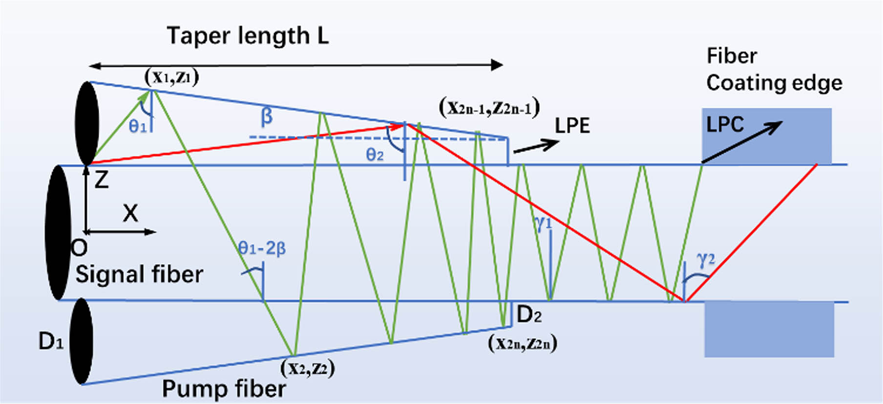
Figure 1.Pump light with different NAs transmitting in the (2 + 1) × 1 side pumping combiner.
When
When
Through the iterative method, the propagation paths of the incident light with different NAs could be calculated by using Eqs. (1)–(4). When the value of
According to the geometric optical theory, we calculated the transmission trajectory of the incident light with two different NAs in the side pumping combiner, which is shown in Fig. 2. As shown in Fig. 2, the green line (pump light with
![]()
Figure 2.Transmission paths of pump light with different NAs in the combiner calculated through the geometric method.
3. Experimental Results
Figure 3 gives the fabrication scheme and end face microscope graph (inserted picture) of a
![]()
Figure 3.(a) Schematic diagram of the manufacturing system of the combiner, insert: a side microscope picture of the manufactured side pump combiner; (b) the physical picture of a combiner packaged in copper fixture.
As illustrated in the theoretical analysis, the initial coupling position to the signal fiber for the pump light varies greatly in the LD pumping and YDFL pumping schemes. During the production process, only part of the tapered pump fiber can be spliced to the surface of the central fiber; therefore, the different fusion areas will affect the performance of the combiner under different pumping schemes. During the specific fabrication, the fusion area could be adjusted through changing the attached portion of the tapered pump fibers to the signal fiber and the lateral position of the heating flame. Under the conditions where the fusion time (60 s), the cone length (1.8 cm), and the waist diameter (10 µm) of the tapered pump fiber remained unchanged, side pump combiners with different fusion areas were prepared. The scanning diagrams of the fusion area of the two side pump combiners are shown in Fig. 4. The black curve is the tapered pump fiber, and the shaded area is the fusion area of the tapered pump fiber and central fiber. Limited by the size of the torch, the length of the fusion zone was kept constant (about 1 cm) in the fabrication. In order to verify the correctness of the experiment, two samples were made in each fabrication parameter: the fusion areas of combiner 1 and combiner 2 are illustrated in Fig. 4(a), while the fusion areas of combiner 3 and combiner 4 are illustrated in Fig. 4(b).
![]()
Figure 4.Scanning diagrams of fusion areas of different side pumping combiner samples; (a), (b) represent the fabrication parameters of combiners designed for LD pumping and YDFL pumping, respectively.
The divergence angle of the LD and YDFL pump source used in the test process is measured through a CCD camera (Thorlabs, BC106N-VIS/M), and the corresponding NA is thereafter calculated as 0.17 and 0.05, respectively. The coupling efficiency and signal insertion loss test results are given in Table 1. Due to the relatively low coupling efficiency, the pump power in the test process is lower than 100 W here for the sake of security, and the high-power testing results will be given in the next section. As evident in Table 1, in terms of pump coupling efficiency, combiners 1 and 2 perform better than combiners 3 and 4 in the case of LD pumping, but in the case of YDFL pumping, the results are just the opposite. The reason why combiners 1 and 2 have a relatively low coupling efficiency in the YDFL pumping scheme is that only the starting end of the tapered pump fiber is spliced into the central fiber. As illustrated in Fig. 2, the high-brightness pump light from the YDFL has not been completely reflected into the signal fiber and will leak as LPE from the pump pigtail, decreasing the coupling efficiency. However, for combiners 3 and 4, the starting end of the tapered pump fiber is partly spliced into the central fiber. Therefore, high NA pump light will be limited in the pump fiber and cannot transmit into the central fiber in this area. Subsequently, within the same longitudinal distance in the combiner, the reflection number for the pump light will increase, so will the divergence angle of the pump light, which will cause more light to leak as LPC and decrease the coupling efficiency. The signal insertion loss of the combiner is measured through a 1064 nm single-mode fiber laser source. As described in Ref. [21], the insertion loss for the signal fiber of the side pumping combiner is closely related the flame temperature. For combiners 3 and 4, the waist diameter of the tapered pump fiber in the fusion area is much smaller than that of combiners 1 and 2. In this case, a relatively low flame temperature can fuse the tapered portion into the central fiber and therefore ensure a high coupling efficiency of the combiner when pumping with high-brightness YDFL. Subsequently, smaller impact and insertion loss will be introduced to the signal fiber in the combiner fabricated for YDFL pumping when compared with the combiner fabricated for LD pumping.
| LD Pump Efficiency (%) | YDFL Pump Efficiency (%) | Signal Insertion Loss (%) | |
|---|---|---|---|
| Combiner 1 | |||
| Combiner 2 | |||
| Combiner 3 | |||
| Combiner 4 |
Table 1. Relationship between the Pump Coupling Efficiency and the Signal Insertion Loss of Different Side Pump Combiners with Different Pump Sources
As shown in Fig. 5, two LDs (Reci, DAB1200, wavelength 915 and 976 nm) were utilized to test the characteristics of combiner 1 in high-power operation. An endcap was spliced with the output signal fiber of combiner 1 in order to decrease the backward light and protect the system. The packaged combiner was placed on a heat sink (keeping temperature of 20°C with the assistance of water cooling), and the working temperature of the system was monitored by a thermal imager.
![]()
Figure 5.Experimental setup of the coupling efficiency and temperature characteristic testing system of combiner 1 (with LD pumping).
The testing results of combiner 1 are illustrated in Fig. 6. As evident in Fig. 6, the output power of the combiner increases linearly with the input pump power, the peak value is 2179 W when the pump power of 2267 W is injected, and the corresponding coupling efficiency is about 97%. Moreover, the highest temperature of the side pump combiner also increases as the input pump power increases linearly with a coefficient of 12.41°C/kW. The thermal picture inserted in Fig. 6 shows the temperature characteristics of combiner 1 working with 2267 W LD pump power injected. The highest temperature (50°C) is located at the edge of the coating of the central fiber, which determines the power tolerance of the side pump combiner.
![]()
Figure 6.Results of pump coupling efficiency and temperature characteristics of combiner 1 when pumped with the LD. Insert: the thermal picture of the home-made side pumping combiner when injecting 2267 W LD pump power.
The high-power test scheme of combiner 3 with YDFL pumping is given in Fig. 7, which is similar to Fig. 5, except that the pumping source was replaced by a combined high-brightness 1018 nm YDFL (each YDFL with a core diameter of 10 µm). The test results are shown in Fig. 8. From this figure, the output power increases linearly with the increase of input power with a coefficient of 99%.
![]()
Figure 7.Experimental setup of the coupling efficiency and temperature characteristic testing system of combiner 3 (with YDFL pumping).
![]()
Figure 8.Results of pump coupling efficiency and temperature characteristics of combiner 3 when pumped with the YDFL. Insert: the thermal picture of the home-made side pumping combiner when injecting 2730 W YDFL pump power.
Besides, the highest temperature of the side pumping combiner also increases linearly with the increase of input pump power with a coefficient of 6.5°C/kW. It is worth noting that combiner 3 performs better than combiner 1 in terms of pump coupling efficiency and temperature characteristics thanks to the high-brightness pump source from the YDFL, proving the potential of the pumping capacity improvement through the side pumping combiner and tandem pumping scheme. The picture inserted in Fig. 8 shows the thermal picture of combiner 3 working with 2730 W YDFL injected from one pump port. Through experimental measurement, the other pump port performs similarly to the previous tested port.
4. Discussion and Conclusion
The experiment reveals that first, to improve the coupling efficiency, the fabricated parameters for side pumping combiners designed for LD pumping and YDFL pumping are different: for LD pumping application, the starting end of the tapered pump fiber should be fused into the central fiber, while for YDFL tandem pumping, the waist of the tapered pump fiber should be fused into the central fiber. Second, the pump light from the YDFL has a smaller divergence angle when propagating in the combiner, which will decrease the power because of LPC. Subsequently, the coupling efficiency and temperature characteristics of the side pumping combiner in this case are better than that directly pumped by the LD source. Moreover, for the side pumping combiner designed for YDFL pumping application, the waist size of the tapered pump fiber in the fusion area is much smaller, which means that a low flame temperature during the fusion process is enough to ensure a high coupling efficiency. Thereafter, when compared with the combiner designed for LD pumping, the combiner designed for YDFL pumping performs better in insertion loss and beam quality characteristics of the signal fiber.
In summary, this paper investigated the performance of a
References
[1] D. J. Richardson, J. Nilsson, W. A. Clarkson. High power fiber lasers: current status and future perspectives. J. Opt. Soc. Am. B, 27, B63(2010).
[2] S. D. Jackson. Towards high-power mid-infrared emission from a fiber laser. Nat. Photon., 6, 423(2012).
[3] H. Chen, X. Jiang, S. Xu, H. Zhang. Recent progress in multi-wavelength fiber lasers: principles, status, and challenges. Chin. Opt. Lett., 18, 041405(2020).
[4] H. Xiao, P. Zhou, X. L. Wang, S. F. Guo, X. J. Xu. High power 1018 nm monolithic Yb3+-doped fiber laser and amplifier. Laser Phys. Lett., 9, 748(2012).
[5] Z. Wang, P. Yan, Y. Huang, J. Tian, C. Cai, D. Li, Y. Yi, Q. Xiao, M. Gong. An efficient 4-kW level random fiber laser based on a tandem-pumping scheme. IEEE Photon. Technol. Lett., 31, 817(2019).
[6] M. Hu, Z. Quan, J. Wang, K. Liu, X. Chen, C. Zhao, Y. Qi, B. He, A. Zhou. Stimulated Brillouin scattering threshold dependent on temporal characteristics in a kilowatt-peak-power, single-frequency nanosecond pulsed fiber amplifier. Chin. Opt. Lett., 14, 031403(2016).
[7] B. Yang, H. Zhang, C. Shi, R. Tao, R. Su, P. Ma, X. Wang, P. Zhou, X. Xu, Q. Lu. 3.05 kW monolithic fiber laser oscillator with simultaneous optimizations of stimulated Raman scattering and transverse mode instability. J. Opt., 20, 025802(2018).
[8] C. Lei, Z. Chen, J. Leng, Y. Gu, J. Hou. The influence of fused depth on the side-pumping combiner for all fiber lasers and amplifiers. J. Lightwave Technol., 35, 1922(2017).
[9] D. Wang, Y. Wang, S. Liu. New reflecting side-pumped method of double-clad fiber laser by micro-prism. Acta Opt. Sin., 29, 974(2009).
[10] J. P. Koplow, L. Goldberg, D. A. V. Kliner. Compact 1-W Yb-doped double-cladding fiber amplifier using V-groove side-pumping. IEEE Photon. Technol. Lett., 10, 793(1998).
[11] J. P. Koplow, S. W. Moore, D. A. V. Kliner. A new method for side pumping of double-clad fiber sources. IEEE J. Quantum Electron., 39, 529(2003).
[12] S. L. Lin, Y. W. Lee, K. Y. Hsu, C. W. Huang, S. L. Huang. Design of resonantly side-pumped 1645-nm Er:YAG crystal fiber lasers with grating couplers. Conference on Lasers and Electro-Optics Pacific Rim (CLEO-PR), TuA1_5(2013).
[13] T. Theeg, H. Sayinc, J. Neumann, L. Overmeyer, D. Kracht. Pump and signal combiner for bi-directional pumping of all-fiber lasers and amplifiers. Opt. Express, 20, 28125(2012).
[14] Q. Xiao, P. Yan, H. Ren, X. Chen, M. Gong. A side-pump coupler with refractive index valley configuration for fiber lasers and amplifiers. J. Lightwave Technol., 31, 2715(2013).
[15] Q. Tan, T. Ge, X. Zhang, Z. Wang. Cascaded combiners for a high power CW fiber laser. Laser Phys., 26, 025102(2016).
[16] D. Fanlong, Z. Xinhai, S. Feng. Side coupler applied in a multi-pumped Yb-doped triple-clad fiber laser. Laser Phys., 28, 125106(2018).
[17] Q. Xiao, D. Li, Y. Huang, X. Wang, Z. Wang, J. Tian, P. Yan, M. Gong. Directly diode and bi-directional pumping 6 kW continuous-wave all-fibre laser. Laser Phys., 28, 125107(2018).
[18] Y. Gu, C. Lei, J. Liu, R. Li, L. Liu, H. Xiao. Side-pumping combiner for high-power fiber laser based on tandem pumping. Opt. Eng., 56, 116109(2017).
[19] Z. Wang, W. Yu, J. Tian, T. Qi, D. Li, Q. Xiao, P. Yan, M. Gong. 5.1 kW tandem-pumped fiber amplifier seeded by random fiber laser with high suppression of stimulated Raman scattering. IEEE J. Quantum Electron., 57, 6800109(2020).
[20] Z. Li, M. Fu, X. Tian, X. Zhao, H. Li, Z. Chen, Z. Wang, J. Chen. Investigation of the pump coupling efficiency of a side-pumping combiner based on tapered-fused method. Opt. Express, 29, 17784(2021).
[21] C. Lei, Z. Chen, H. Yang, Y. Gu, H. Jing. Beam quality degradation of signal light in a side pumping coupler with a large-mode-area signal fiber. Opt. Express, 27, 14041(2019).


Set citation alerts for the article
Please enter your email address

© Copyright 2018-2021 | Chinese Laser Press. All Rights Reserved 沪ICP备15018463号-20