• Chinese Optics Letters
  • Vol. 18, Issue 12, 122201 (2020)
A. Garza-Rivera1, J. E. Gómez-Correa2、*, F. J. Renero-Carrillo1, J. P. Trevino3, and V. Coello4
Author Affiliations
  • 1INAOE, Departamento de Óptica, Tonantzintla, Puebla, 72840, Mexico
  • 2Catedras Conacyt – CICESE, Unidad Monterrey, PIIT Apodaca, Nuevo León, 66629, Mexico
  • 3Tecnológico de Monterrey, Campus Puebla, Departamento de Bioingeniería y Ciencias, Puebla, Puebla, 72453, Mexico
  • 4CICESE, Unidad Monterrey, PIIT Apodaca, Nuevo León, 66629, Mexico
  • show less
    DOI: 10.3788/COL202018.122201 Cite this Article Set citation alerts
    A. Garza-Rivera, J. E. Gómez-Correa, F. J. Renero-Carrillo, J. P. Trevino, V. Coello. Gabor superlens with variable focus[J]. Chinese Optics Letters, 2020, 18(12): 122201 Copy Citation Text show less

    Abstract

    In this Letter, a Gabor superlens with variable focus is presented. This configuration uses tunable liquid lenses in the third microlens array of the Gabor superlens. By applying voltage, the radius of curvature of the micro-tunable doublet arrays changes, and the Gabor conditions are fulfilled at different focal planes. As a consequence, the magnification of the image at the focal planes changes, and a zoom effect is observed. The marginal depth plane for this system goes from 0.86 to 0.89 mm. The optical simulation, calculations, and results of the simulated optical system performance are presented.

    In 1940, Denis Gabor proposed a system that, by using a set of microlens arrays (MLAs), forms an erect image whose relative position is a function of the object distance, i.e., it could be seen as a synthetic superposition compound eye. Such a configuration is currently known as the “Gabor superlens” (GSL)[1]. GSL had been inspired by multi-aperture optical systems that are present in compound eyes. This kind of eye has the advantage of being capable of processing a large amount of input information from the environment, without saturating the neural system of the organism. The mechanism by which the small faceted eyes form the image of an object has sparked the idea of developing non-conventional optical systems that will profit from those capabilities. The multi-aperture optical devices could be used in image forming applications, optical communications, and medical instruments, among others. For instance, in free space optical communication systems, it is possible to have signal multiplexers, demultiplexers, and switches using a GSL configuration[2]. Since this configuration performs integral imaging, the axes of bundles of light rays coming from different object positions intersect. Also, integral imaging is a very promising technology for three-dimensional (3D) displays. With this technique, it is possible to form an image by concentrating light rays through a lens array. It has the advantage that the viewer does not need to wear glasses required by ordinary stereoscopic 3D displays, neither does it need to process a lot of information like in holography[3,4].

    On the other hand, a tunable liquid lens, or electrowetting lens, is a lens that changes curvature when a voltage is applied, whereas a different alternative is a liquid crystal, which has a short response time and low operation voltage[5,6]. A change like this shifts the focal distance of the lens[7]. This process has several similitudes with the accommodation of the human eye[8] due to the fact that the human crystalline lens adjusts its shape to correctly focus the eye in response to visual demand[810] rather than shifting its position as other mechanical systems. For this reason, the tunable liquid lens has been considered as an option for developing bionic eyes to mimic the function of the human crystalline lens[11].

    In this Letter, for the first time, to the best of our knowledge, a design of a GSL capable of performing a zoom function and changing its focal distance using an array of micro-tunable liquid lenses is presented. The use of a micro-tunable liquid lens array, instead of the conventional MLA basic design, makes it possible to achieve different values of the global focal length and the optical power of each configuration as a function of the change of curvature. With a varifocal system, as the one presented here, the function of focusing a signal with different intensities at different planes will enable the design of more robust and versatile devices. There are several possible designs for tunable lenses. Specifically, this work is based on the research of Kuiper et al.[12], who showed that the variation of focal length is a function of the radius of curvature of the meniscus of a liquid lens that works by electrowetting.

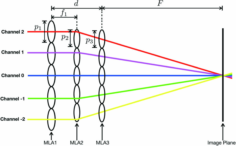
    The GSL consists of an array of off-axis micro-Keplerian telescopes (MKTs), in which a beam of light that enters the system is deflected by an angle that changes with the focal lengths of the lenses and their relative displacement[13]. A collimated incident beam would be divided into arrays of smaller beams, which would converge to a common point of minimum confusion, producing a finite conjugate image. The first MLA performs the function of an objective lens and produces multiple real images that are transferred afterwards to the image plane by a relay MLA. At the center of the GSL, three lenses on each MLA are aligned on a common optical axis. As the microtelescope (which can be called an optical channel) is displayed by the smaller pitch of the relay array, it produces the image translation required to properly register the composite image[14]. The MLAs are characterized as follows. The focusing lens array (MLA1) with pitch p1 and focal length f1 focuses the light in the intermediate image plane (object assumed to be at infinity). The field lens array (MLA2) with pitch p2 and focal length f2 is located in the intermediate image plane and redirects all light of the intermediate images into the relay lens array. The relay lens array (MLA3) with pitch p3 and focal length f3 magnifies the intermediate images onto the detector, as shown in Fig. 1.

    Microlens array of a Gabor superlens.

    Figure 1.Microlens array of a Gabor superlens.

    A GSL has to fulfill the “Gabor condition” or “superposition condition,” which states that all optical rays with the same incident field of view (FOV) angle must focus at the same image point regardless of the path they follow[13,14]. From this condition, for a three-element GSL, it follows where F is the back focal distance, and d is the distance from the center of MLA1 to the center of MLA3, as shown in Fig. 1.

    The optical design method proposed consists of the calculation, simulation, and optimization of the central unit, which performs the same function as an “ommatidia” in a superposition compound eye[15].

    In order to estimate the image quality of an optical system, Seidel aberrations should be calculated. For the GSL, all of the aberrations increase with channel height, and first-order design parameters have a great influence on their value. It has been demonstrated that the aberrations of decentered optics are functions of the aberrations of the central channel[16]. For micro-optical systems, traditional simulation methods cannot be used strictly because diffraction effects gain importance.

    An important concept in addition to the GSL is a micro-tunable lens. A micro-tunable lens is defined as a meniscus between two immiscible liquids that change its curvature and leads to a change in focal distance by means of electrowetting[12]. The parameters of a liquid tunable lens that works by electrowetting are shown in Fig. 2.

    Parameters of a liquid tunable lens that works by electrowetting.

    Figure 2.Parameters of a liquid tunable lens that works by electrowetting.

    The main equations used to describe a tunable lens that works by electrowetting are where O is the optical power, f is the focal length, nc is the refractive index of the conducting liquid, ni is the refractive index of the insulating liquid, and rc is the lens meniscus radius. An electromechanical force changes rc, so a change in the contact angle θ of the conducting liquid with the wall is described by where θ0 is the contact angle in the off state, ε is the dielectric constant of the insulator, t is the thickness, γci is the interfacial tension between the conducting and insulating liquid, and V is the applied voltage.

    The relationship of the meniscus radius rc, the cylinder radius R, and the contact angle θ can be calculated with so, to establish a relationship between optical power and voltage, where O0 is the optical power calculated at the off-state contact angle.

    To design a GSL with varible focus, it is necessary to implement, in the third MLA, a set of liquid micro-tunable lenses that change their curvatures and focus light at different planes. These liquid tunable microlenses have parameter values of nc=1.33, ni=1.52944, R=33μm, ε=2.78901×10¹¹F·m1, γci=0.040N·m1, θ0=π rad, and a lens thickness of d=20μm, where these values were obtained experimentally by Kuiper et al.[12]. The modified GSL array is shown in Fig. 3.

    Micro-tunable lenses are placed in the third array (MLA3).

    Figure 3.Micro-tunable lenses are placed in the third array (MLA3).

    The variation of the second radius of the liquid micro-tunable lens as a function of voltage between 0 V and 115 V is shown in Fig. 4. It can be observed that a change in the meniscus at the interface between the two liquids produces a converging lens for voltages above 90 V. For the voltage values lower than 90 V, a diverging lens is produced. The calculation allows us to bound the voltage range to activate the lens as a converging lens. The proposed system works with the variable curvatures of the contact meniscus produced by a voltage ranging from 100 V to 115 V.

    Variation of the second radius of curvature produced by a voltage range between 0 V and 115 V.

    Figure 4.Variation of the second radius of curvature produced by a voltage range between 0 V and 115 V.

    The simulation of the complete system was done using the non-sequential mode of Opticstudio 18. This simulation is done under the assumption that when the microlens diameter and diffraction limited spot are of the same order, diffraction effects are not critical[14], and, therefore, it is reasonable to leave the diffraction effect out. The final design was simulated according to the Gabor conditions and each element of the third array (MLA3) has a micro-tunable doublet with a planar first surface and a tunable curvature for the second surface, which forms a meniscus on the contact interface between the two liquids when voltage is applied; it is very important to say that the radius of curvature of the third surface of the liquid micro-tunable lens is fixed, and it is 0.1mm. To fulfill these requirements, it is important to calculate the correct pitch difference between the arrays, the exact position of the microlenses, the object position, and the focal length variations in the optical axis, as shown in Table 1.

    Corresponding LensSurface #Radius of Curvature Rc (μm)Thickness t(μm)Refractive Index (ni)Pitch (μm)
    Object1
    MLA12162301.563840100
    3−6501901.000000
    MLA24165201.78472084
    5−1641691.000000
    MLA36101.52944066
    7rc101.337774
    8−1004221.000000
    Image Plane9F

    Table 1. Optical Parameters of the GSL System When the Second Radius of Curvature of the Liquid Micro-Tunable Lens Is rc and Gabor Focal Length Is Fa

    As shown by the simulations, it is possible to see a unique erect image at the common focal point (Fig. 5). The spot formed by the optical system is registered by a simulated detector at the image plane (Fig. 6). In the detector, it could be observed and quantified that the spot size is different for each voltage and curvature. Each spot is detected as incoherent irradiance as a function of spatial position. This means that it registers the power of each ray that strikes the same pixel and adds it, keeping track of the phase of each ray. The final amplitude is squared to yield the coherent power. For different values of the Gabor focus, different peak irradiances are obtained (see Table 2) as well as different focal spot sizes, as shown in Fig. 6. For this reason, an aberration analysis was done using the mixed mode of Opticstudio 18. Different voltages generating several different curvatures were taken into account. Each case produced a different effective focal length. The aberration analysis for each surface through each of the three different symetrical channels (Channels 0, 1, and 2) was calculated, and the total Seidel aberration coefficients of the system were plotted (Fig. 7). It might seem unexpected that as the peak values of the Seidel aberration coefficients increase, the focal spot size decreases. However, looking at the ray tracing near the focal plane in Fig. 8, it is readily observed that as the longitudinal aberration increases, the transverse decreases, while the total Seidel coefficients increase. This observation is consistent with the focal spot size decrease as the total Seidel aberrations increase.

    Simulation of GSL with an array of micro-tunable liquid lens with V=115 V and a radius of curvature of −0.061 in the middle surface of the third array.

    Figure 5.Simulation of GSL with an array of micro-tunable liquid lens with V=115V and a radius of curvature of −0.061 in the middle surface of the third array.

    Spot registered by the detector in the simulation of the GSL with an array of micro-tunable liquid lenses as MLA3 applying a voltage (V) and a radius of curvature (rc) in the middle surface of the third array: (a) V=0 V and rc=∞, (b) V=100 V and rc=−0.204, (c) V=105 V and rc=−0.117, (d) V=110 V and rc=−0.081, and (e) V=115 V and rc=−0.061.

    Figure 6.Spot registered by the detector in the simulation of the GSL with an array of micro-tunable liquid lenses as MLA3 applying a voltage (V) and a radius of curvature (rc) in the middle surface of the third array: (a) V=0V and rc=, (b) V=100V and rc=0.204, (c) V=105V and rc=0.117, (d) V=110V and rc=0.081, and (e) V=115V and rc=0.061.

    Total Seidel aberration coefficients plotted for increasing values of the focal distance. Observe that the central channel with all aberrations is close to zero except for the spherical aberration, as shown in (a). Other channels show an increase of all aberration coefficients except for field curvature, as shown in (b) and (c).

    Figure 7.Total Seidel aberration coefficients plotted for increasing values of the focal distance. Observe that the central channel with all aberrations is close to zero except for the spherical aberration, as shown in (a). Other channels show an increase of all aberration coefficients except for field curvature, as shown in (b) and (c).

    Zoom of the ray tracing at the detector (image plane) of the GSL system with (a) V=100 V and rc=−0.204, and (b) V=115 V and rc=−0.061. An apparent trade-off between transverse and longitudinal ray aberrations is observed as a zoom is performed close to the focal plane. This explains the behavior of the focal spot size as the focal distance varies.

    Figure 8.Zoom of the ray tracing at the detector (image plane) of the GSL system with (a) V=100V and rc=0.204, and (b) V=115V and rc=0.061. An apparent trade-off between transverse and longitudinal ray aberrations is observed as a zoom is performed close to the focal plane. This explains the behavior of the focal spot size as the focal distance varies.

    Voltage (V)Peak Incoherent Irradiance [(W/cm)2]
    01.050×10⁷
    1001.600×107
    1053.000×107
    1106.650×107
    1152.855×108

    Table 2. Peak Incoherent Irradiance Distribution for Each Voltage

    The calculated values show clearly the best position for the different image planes. Also, the focal length of the doublets decreases as the Gabor focal length of the system increases, as shown in Table 3.

    Voltage (V)Radius of Curvature rc (mm)Focal Length of the Doublets f (mm)Gabor Focal Length F (mm)
    100−0.2040.23240.86
    105−0.1170.20250.87
    110−0.0810.17600.88
    115−0.0610.15430.89

    Table 3. Radius of Curvature (rc), Focal Length of the Doublets f, and Gabor Focal Length (F) of the GSL System as Functions of the Change of Voltage from 100 V to 115 V

    In conclusion, a new GSL capable of varying its focal length was presented. This was achieved by applying an electric current to the third MLA, which allowed it to change its inner radius of curvature. This change made to MLA3 generates a change in the focal length of the entire system of the new GSL. The spot size and the intensity distribution (incoherent irradiance) at the detector plane were different for each value of voltage within the range that produces a converging lens. At the moment when the Gabor focal length increases, the intensity value of the spot formed in the detector increases as well. This means that, for each different curvature, the best focal plane changes position, and therefore an optical zoom effect is achieved. Two advantages of this kind of system over a mechanical zoom system are its robustness and the fact that there is no need to move the lens. In addition to liquid lenses, the proposed superlens configuration may also be explored by using other tunable MLAs such as liquid crystal lenses that are free from gravity-induced distortion[5,6]. The applications of a non-conventional multi-aperture optical system like this are among many: miniaturization, wider FOV, adjustment to complex free form surfaces, laser controlled focusing, non-guided optical communications, and more to be found.

    A. Garza-Rivera, J. E. Gómez-Correa, F. J. Renero-Carrillo, J. P. Trevino, V. Coello. Gabor superlens with variable focus[J]. Chinese Optics Letters, 2020, 18(12): 122201
    Download Citation