
Zhiyu Chen, Xin Zhong, Lin Jiang, Jiaxin Xu, Jingxian Liu, Yan Pan, Tao Zhou. Linearized microwave downconversion link based on fast and intelligent impairment equalization for noncooperative systems[J]. Chinese Optics Letters, 2023, 21(2): 023902
- Chinese Optics Letters
- Vol. 21, Issue 2, 023902 (2023)
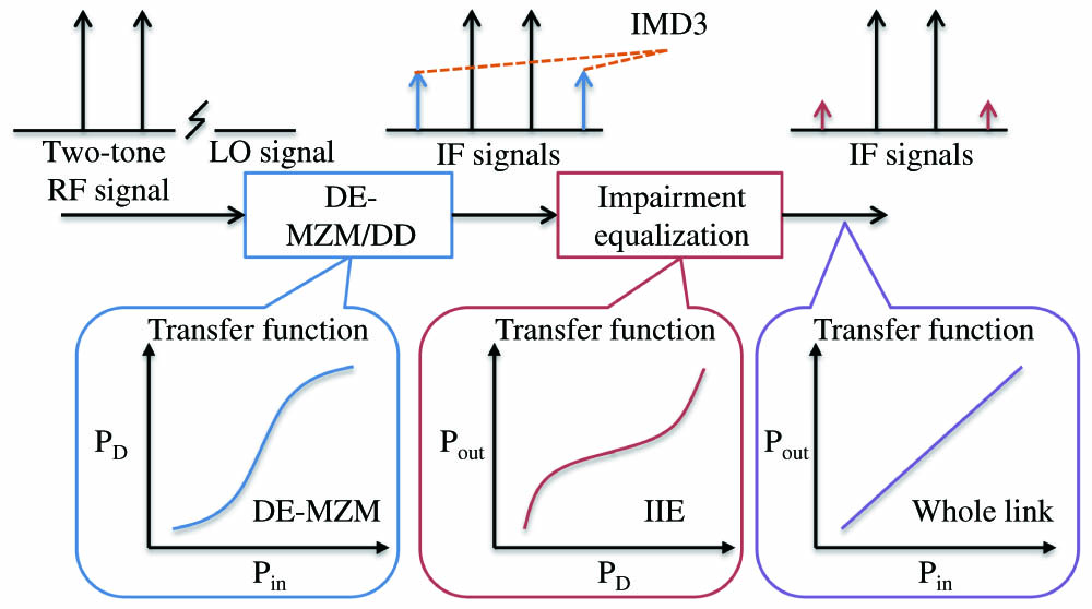
Fig. 1. Simplified diagram of linearized downconversion link and corresponding signal spectra and transfer characteristics. DE-MZM/DD, dual-electrode Mach–Zehnder modulated direct detection; IMD3, third-order intermodulation distortion; IIE, intelligent impairment equalization; RF, radio frequency; IF, intermediate frequency.
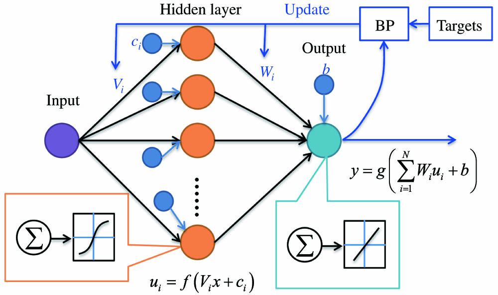
Fig. 2. Equalization-based inverse link transfer function estimation. BP, backpropagation.
Fig. 3. Experimental setup of proposed linearized microwave downconversion link. LD, laser diode; PC, polarization controller; DE-MZM, dual-electrode Mach–Zehnder modulator; LO, local oscillator; EDFA, erbium-doped fiber amplifier; PD, photodetector; IIE, intelligent impairment equalization.
Fig. 4. (a) Dependence of MSE on the number of epochs for the training subsets; inset, the electrical spectrum of two-tone signal with the MSE of 10−6; (b) DE-MZM/DD-based transmission link and calculated inverse link transfer functions; black solid curve, theoretical inverse transfer function; red dotted curve, IIE-based inverse link transfer function; inset, whole downconversion link transfer characteristic by applying IIE.
Fig. 5. Electrical spectra of the two-tone input tests before and after applying IIE when the frequencies are set to be (a), (b) 2.11 GHz and 2.13 GHz; (c), (d) 2.10 GHz and 2.14 GHz; and (e), (f) 4.11 GHz and 4.13 GHz, respectively.
Fig. 6. Measured SFDR before (solid line) and after (dashed line) IIE.

Set citation alerts for the article
Please enter your email address
© Copyright 2018-2021 | Chinese Laser Press. All Rights Reserved 沪ICP备15018463号-20