• Photonics Research
  • Vol. 11, Issue 7, 1162 (2023)
Xinmin Fu1、†, Jie Yang1、2、†, Jiafu Wang1、2、3、*, Yajuan Han1、4、*, Chang Ding1, Tianshuo Qiu1, Bingyue Qu2, Lei Li1, Yongfeng Li1, and Shaobo Qu1
Author Affiliations
  • 1Shaanxi Key Laboratory of Artificially-Structured Functional Materials and Devices, Air Force Engineering University, Xi’an 710051, China
  • 2School of Electronic and Information Engineering, Xi’an Jiaotong University, Xi’an 710049, China
  • 3e-mail: wangjiafu1981@126.com
  • 4e-mail: mshyj_mail@126.com
  • show less
    DOI: 10.1364/PRJ.473698 Cite this Article Set citation alerts
    Xinmin Fu, Jie Yang, Jiafu Wang, Yajuan Han, Chang Ding, Tianshuo Qiu, Bingyue Qu, Lei Li, Yongfeng Li, Shaobo Qu. Completely spin-decoupled geometric phase of a metasurface[J]. Photonics Research, 2023, 11(7): 1162 Copy Citation Text show less

    Abstract

    Metasurfaces have provided an unprecedented degree of freedom (DOF) in the manipulation of electromagnetic waves. A geometric phase can be readily obtained by rotating the meta-atoms of a metasurface. Nevertheless, such geometric phases are usually spin-coupled, with the same magnitude but opposite signs for left- and right-handed circularly polarized (LCP and RCP) waves. To achieve independent control of LCP and RCP waves, it is crucial to obtain spin-decoupled geometric phases. In this paper, we propose to obtain completely spin-decoupled geometric phases by engineering the surface current paths on meta-atoms. Based on the rotational Doppler effect, the rotation manner is first analyzed, and it is found that the generation of a geometric phase lies in the rotation of the surface current paths on meta-atoms. Since the induced surface current paths under the LCP and RCP waves always start oppositely and are mirror-symmetrical with each other, it is natural that the geometric phases have the same magnitude and opposite signs when the meta-atoms are rotated. To obtain spin-decoupled geometric phases, the induced surface current under one spin should be rotated by one angle while the current under the other spin is rotated by a different angles. In this way, LCP and RCP waves can acquire different geometric phase changes. Proof-of-principle prototypes were designed, fabricated, and measured. Both the simulation and experiment results verify spin-decoupled geometric phases. This work provides a robust means to obtain a spin-dependent geometric phase and can be readily extended to higher frequency bands such as the terahertz, IR, and optical regimes.

    1. INTRODUCTION

    Freely customizing the properties and functions of available materials is the persistent pursuit of scientists, scholars, and engineers. Metasurfaces, which are planar arrays of subwavelength metallic or dielectric structures (meta-atoms), provide a robust way to customize properties because they allow an unprecedented degree of freedom (DOF) to manipulate electromagnetic (EM) waves [14]. By changing the geometrical parameters or orientation of meta-atoms, the amplitude [5], phase [6,7], and polarization [8] of the EM waves can be tailored to implement functional devices such as planar focusing lenses [9], planar retroreflectors [10,11], and holographic imagers [12,13]. Among them, metasurfaces have played very important roles in phase control and different kinds of phases can be obtained using metasurfaces.

    In general, the phases imparted by metasurfaces mainly include four types: a resonance phase, a propagation phase, a detour phase, and a geometric phase. The resonance phase results from the localized electron oscillation within meta-atoms and is typically a Lorentzian type [14]. The propagation phase is an accumulated phase during electromagnetic wave propagation within materials that depends on the material thickness and wavelength [6,15]. The detour phase only appears under oblique incidence and is strongly dispersive both in the frequency domain and in the spatial domain [16,17]. The three kinds of phases above all result from localized resonances within or between meta-atoms. Therefore, they are all narrowband, which restricts their application in the development of broadband or even wideband functional devices. To obtain wideband phase control, the geometric phase is usually introduced by rotating meta-atoms by sequences. This type of phase is also known as a Pancharatnam–Berry (P-B) geometric phase and is usually nondispersive in a quite wide band [1821]. P-B geometric phases have brought great impetus to the development of wideband functional devices using metasurfaces because of their wideband properties. Nevertheless, there is still an underlying dilemma for geometric phases obtained by rotating meta-atoms. A rotated meta-atom always imparts geometric phases with the same amplitude and opposite signs for left- and right-handed circularly polarized (LCP and RCP) waves. A P-B geometric phase is usually spin-coupled [6,21], which prohibits independent controls on LCP and RCP waves. To overcome this limitation, a common method combs the spin-coupled geometric phase with the spin-decoupled phase. In this way, the magnitudes or even the signs of geometric phases imparted to LCP and RCP can be changed. For example, bifunctional wavefront-manipulating devices are achieved by combining geometric phases and propagation phases [6,15,22,23]. Furthermore, other combinations, such as the resonance phase and the P–B phase [2429], and the Aharonov–Anandan (A–A) phase and P–B phase [30,31], are also proposed. However, this scheme depends on the introduction of a “third-party” phase, and do not break the spin symmetry of the geometric phases. The geometric phases imparted to LCP and RCP waves are in fact still spin-coupled.

    The question remains: does it come naturally to obtain spin-decoupled geometric phases using metasurfaces without combinations? In this paper, we explore a spin-decoupled geometric phase of a metasurface and propose to obtain spin-decoupled geometric phases by engineering the surface current paths on meta-atoms. To this end, the geometric phase obtained by rotating meta-atoms is first analyzed. It is found that the generation of a geometric phase by rotating meta-atom lies in the rotation of the surface current path. By calculating the rotational Doppler effect, we found the relationship between the current rotation and the geometric phase. The rotation angle of the current path determines the amplitude of the geometric phase, and the relative relationship between the rotation direction and the spin direction determines the sign of the geometric phase. The induced surface current paths under LCP and RCP waves always start oppositely and flow along the metallic structure; once the meta-atom rotates, the surface currents will rotate in the same direction. Because of the difference in the spin directions, the geometric phases should have the same magnitude and opposite signs when the meta-atoms are rotated, as is shown in Fig. 1(a). Within this in mind, to obtain spin-decoupled geometric phases, the induced surface current under one spin should be rotated by an angle while that under the other spin is rotated by different angles. In this way, LCP and RCP waves can acquire different geometric phase changes from a metasurface and a spin-decoupled geometric phase can be achieved using this kind of metasurface. As a proof of concept, we used a split-ring resonator (SRR) structure as the meta-atom to demonstrate this method. By changing the arc of the SRR, the rotation of the surface current on the SRR structure can be enforced without rotating the SRR meta-atom. Due to the actual rotation of surface current path, a geometric phase is naturally generated. As is depicted in Fig. 1(b), by separately customizing the start points of the surface currents induced by LCP and RCP waves, completely spin-decoupled geometric phases can be imparted to LCP and RCP waves by the metasurface. Prototypes were designed, fabricated, and measured. Both the simulation and experiment results verify spin-decoupled geometric phases and a spin-decoupled geometric phase can be readily combined with other phases such as a rotation geometric phase. This work provides a robust method to obtain spin-decoupled geometric phases and will further add to the metasurface’s DOF to manipulate EM waves.

    Two geometric phase modulations and their surface currents. The blue arrow represents the surface current JR induced by the RCP, while the red arrow represents the surface current JL induced by the LCP. (a) The spin-coupled P-B phase. When the meta-atom rotates around the center, the surface currents (JR and JL) must rotate along with it. Due to the opposite spin for the RCP and LCP wave, the generated geometric phase is φR=−φL. (b) The spin-decoupled geometric phase. When one end of the circular arc is changed, only the JR rotates, resulting in a geometric phase generated for the RCP wave.

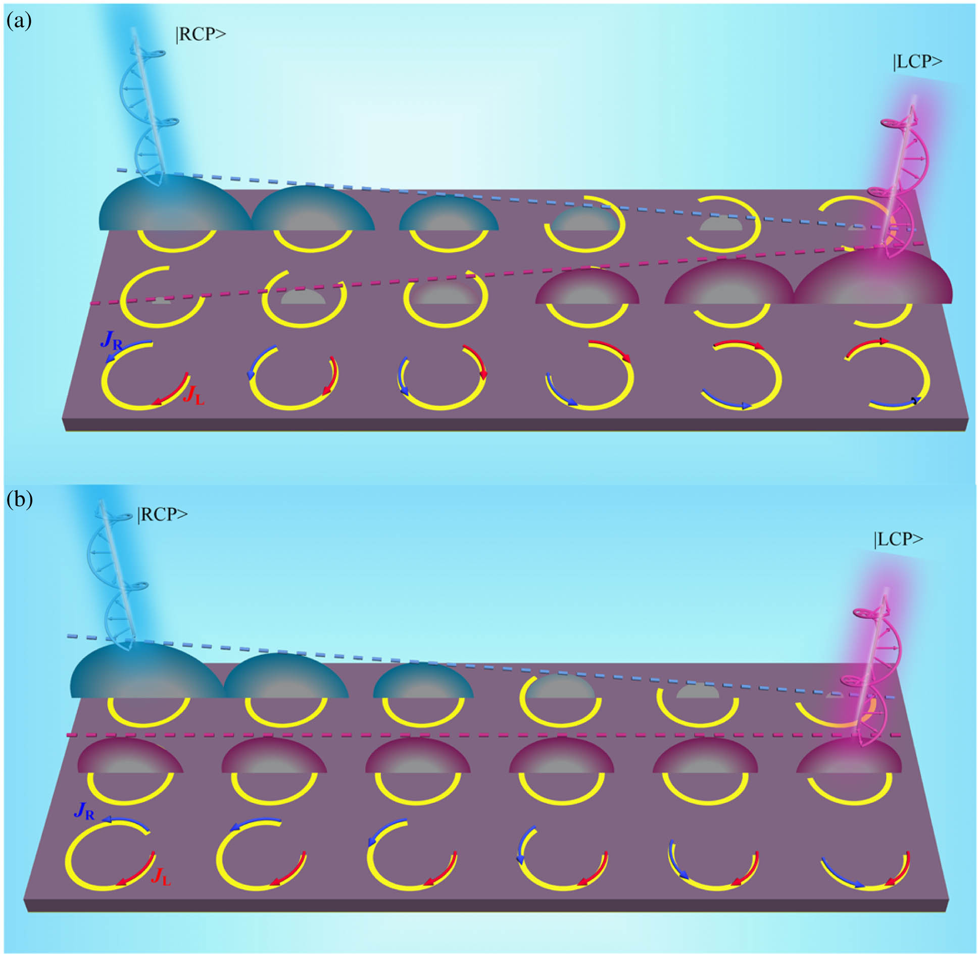
    Figure 1.Two geometric phase modulations and their surface currents. The blue arrow represents the surface current JR induced by the RCP, while the red arrow represents the surface current JL induced by the LCP. (a) The spin-coupled P-B phase. When the meta-atom rotates around the center, the surface currents (JR and JL) must rotate along with it. Due to the opposite spin for the RCP and LCP wave, the generated geometric phase is φR=φL. (b) The spin-decoupled geometric phase. When one end of the circular arc is changed, only the JR rotates, resulting in a geometric phase generated for the RCP wave.

    2. RESULTS AND DISCUSSION

    A. Theory Analysis and Design

    A geometric phase plays an important role in the development of a wideband metasurface due to its wavelength independent and nondispersive properties. Under circularly polarized (CP) wave illumination, a phase with span of 2π and near-unity amplitude can be simultaneously obtained via a metasurface. The conventional way to obtain a geometric phase is by rotating the meta-atoms; that is, φL(R)=±2α, where α is the rotating angle, and ± represents LCP and RCP waves, respectively.

    We choose the simplest dipole structure (a short straight metallic strip), as shown in Fig. 2, to analyze the essential reason to generate geometric phases by rotation. Previous studies have shown that the rotational Doppler shift occurs when a light beam carrying angular momentum propagates through a spinning object along its rotation axis and the Coriolis effect is responsible for it. When a coordinate system is attached to a rotated meta-atom, a rotational system is created. Since the rotating Doppler effect will be generated in the rotation system, we derive the rotational Doppler shift and the resulting geometric phase by establishing Maxwell’s equations under a rotating coordinate system. The geometric phase is expressed as φ=Δωdt=σΩzdt,where Δω is the angular frequency shift resulting from the angular Doppler effect, Ωz is the rotational angular velocity with respect to the dipole, and σ=±1 represents LCP() and RCP(+) waves. More details of this derivation can be found in Appendix A [3234]. The rotation of the dipole around the center represents a conversion of the polarization state, corresponding to the rotation of the polarization ellipse in the Poincaré sphere depicted in Fig. 2. Each longitude line represents an evolutionary state of CP conversion; in addition, a geometric phase state. Figure 2(b) depicts eight of these states [35]. Thus, the angular velocity of the rotation of the coordinate system is transformed into the rotation velocity of the polarization ellipse; i.e., Ωz=d(2τχ)/d(t), where τ=±1 represents the rotation direction of the polarization ellipse (clockwise rotation notated as 1; counterclockwise rotation notated as 1). Then, Eq. (1) becomes φ=2στχ=2δχ,where δ=±1. When the rotation direction is opposite to the spin direction of the incident waves, δ=1; when they are consistent in the direction, δ=1.

    Geometric phase by rotation. (a) Schematic diagram of the Poincaré sphere. (b) Schematic diagram of the evolutionary path for the circular polarization on the Poincaré sphere. IN represents the incident polarization state, and OUT represents the reflected polarization state. The evolutionary path for the circular polarization on the Poincaré sphere must pass a point at the equator (middle row). Each column represents an evolutionary path. The top row is the RCP state, the middle row is the linear polarization state with a different polarization angle, and the bottom row is the RCP state. Green and purple arrows indicate the electric and magnetic fields, and black arrows show the polarization vectors, respectively [32].

    Figure 2.Geometric phase by rotation. (a) Schematic diagram of the Poincaré sphere. (b) Schematic diagram of the evolutionary path for the circular polarization on the Poincaré sphere. IN represents the incident polarization state, and OUT represents the reflected polarization state. The evolutionary path for the circular polarization on the Poincaré sphere must pass a point at the equator (middle row). Each column represents an evolutionary path. The top row is the RCP state, the middle row is the linear polarization state with a different polarization angle, and the bottom row is the RCP state. Green and purple arrows indicate the electric and magnetic fields, and black arrows show the polarization vectors, respectively [32].

    As shown in Fig. 3, under the illumination of CP waves, a surface current will be induced on the metallic structure of a meta-atom. Once the meta-atom rotates, the surface currents must rotate with it. Since the secondary radiation of the surface current actually determines the EM properties of reflected fields, the P-B phase generated by rotation is essentially caused by the rotation of the surface current. In other words, the spatial orientation is the intrinsic reason for the geometric phase generation. Intuitively, the surface current induced by incident waves with different spin directions (LCP or RCP) will start and flow in opposite directions. In this way, when the metallic strip is rotated by angle α, the surface current induced by LCP and RCP waves will also be rotated by angle α relative to the center of the meta-atom. The three rotation states (α=0°, 60°, and 120°) are selected and presented in Fig. 3(a), which shows that, as the meta-atom rotates, the rotation angles of the surface currents under RCP and LCP wave illumination are 0°, 60°, and 120°. However, since the RCP and LCP waves spin in opposite directions, φR=φL, where the φR and φL are the generated geometric phase under RCP and LCP wave illumination, respectively. The right panel of Fig. 3(a) is the simulated reflected phase in the three rotation states. Note that φR and φL exhibit opposite gradient directions. This feature is also known as the spin-locking of P-B phases.

    Geometric phases generated by rotating meta-atom, where α is defined as the rotation angle of the meta-atom, and χ is defined as the rotation angle of the current path. The two meta-atoms have a similar structural form, which is depicted in Fig. 4(a). F4B microwave laminate (εr=2.65, tan δ=0.001) [30] is selected as the dielectric spacer separating the metallic structure and ground sheet and the metallic material is copper (conductivity: 5.8×10⁷ S/m). The length of the dipole structure is equal to the diameter of the SRR structure. The structure parameters of the SRR are presented in Fig. 4. The width of the structure is 0.4 mm. (a) Rotation of the surface current on the short straight strip and the corresponding reflection phases (α=0°, 60°, and 120°). (b) Rotation of the surface current on SRR and the corresponding reflection phases (α=0°, 60°, and 120°). The blue arrow represents the normal direction of the current path. The rotation direction and angle of the current path are indicated by the position change of the arrow around the center.

    Figure 3.Geometric phases generated by rotating meta-atom, where α is defined as the rotation angle of the meta-atom, and χ is defined as the rotation angle of the current path. The two meta-atoms have a similar structural form, which is depicted in Fig. 4(a). F4B microwave laminate (εr=2.65, tanδ=0.001) [30] is selected as the dielectric spacer separating the metallic structure and ground sheet and the metallic material is copper (conductivity: 5.8×10⁷  S/m). The length of the dipole structure is equal to the diameter of the SRR structure. The structure parameters of the SRR are presented in Fig. 4. The width of the structure is 0.4 mm. (a) Rotation of the surface current on the short straight strip and the corresponding reflection phases (α=0°, 60°, and 120°). (b) Rotation of the surface current on SRR and the corresponding reflection phases (α=0°, 60°, and 120°). The blue arrow represents the normal direction of the current path. The rotation direction and angle of the current path are indicated by the position change of the arrow around the center.

    Moreover, we found that when the meta-atom is rotated, the surface current at each point on the structure is also rotated around the center, as illustrated in Fig. 3(a). Therefore, we can convert the straight strip structure into an SRR with radius r, as shown in Fig. 3(b). For the SRR structure, the induced surface currents under LCP and RCP waves always start from the two ends of the opening gap of SRR, respectively, and they also flow in opposite directions. When the SRR meta-atom is rotated, the induced surface currents are also rotated accordingly. The corresponding reflection phase is also given in Fig. 3(b) and is found to be consistent with that of the dipole structure.

    The simulations and analysis indicate that the geometric phase is caused by the rotation of surface current on the meta-atom. The metasurface core is a metallic structure pattern design, which determines the detailed surface current path. This is why metasurface can be customized for EM manipulation. If the surface currents can be rotated by engineering the path, the geometric phase can also be obtained without rotating the meta-atom. The current diagram in Fig. 3(b) shows that the surface currents are induced by RCP and LCP wave flows at the two endpoints of the SRR gap. Considering that the two current paths flow at different starting points, once one endpoint rotates along the arc, the corresponding surface current will be forced to rotate with it, while another surface current induced by an orthogonal spin wave remains unchanged. In this way, the geometric phase gradient can be obtained for the former spin state but not for the other spin state. With this idea in mind, we define β1 and β2 as the angle between, respectively, the upper and lower ends of the opening gap referenced to the x axis. They determine the start points of surface currents induced by the incident LCP and RCP waves. The schematic diagram of the meta-atom and the definition of the geometric parameters are shown in Fig. 4(a). The reflection performance of the meta-atom was first simulated. Circularly polarized (CP) waves are incident along the z direction, while the x and y directions are set as “unit cell” boundary conditions. For more information about the simulation method, see Appendix E. As shown in Fig. 4(b), high-efficiency polarization conversion can be achieved within 8.0–14.0 GHz. Such polarization conversion results from the reversed propagation direction upon reflection. The near-unity reflection magnitude of the SRR meta-atom guarantees the design of a high-efficiency phase-modulation metasurface.

    Spin-decoupled geometric phase obtained by engineering the surface current path on meta-atoms. (a) Schematic diagram of the SRR meta-atom, where P=10.0 mm, d=4.0 mm, r=4.0 mm, and β1=80°, β2=0°. (b) Reflection performances under incident LCP and RCP waves. (c) Surface current paths under different β1: (i) β1=40° (original state), (ii) β1=85°, (iii) β1=130°, and (iv) β1=175°. The top row is the current path under RCP wave illumination, while the bottom row is the current path under LCP wave illumination. The right panel of (c) is the corresponding geometric phase varying with β1.

    Figure 4.Spin-decoupled geometric phase obtained by engineering the surface current path on meta-atoms. (a) Schematic diagram of the SRR meta-atom, where P=10.0  mm, d=4.0  mm, r=4.0  mm, and β1=80°, β2=0°. (b) Reflection performances under incident LCP and RCP waves. (c) Surface current paths under different β1: (i) β1=40° (original state), (ii) β1=85°, (iii) β1=130°, and (iv) β1=175°. The top row is the current path under RCP wave illumination, while the bottom row is the current path under LCP wave illumination. The right panel of (c) is the corresponding geometric phase varying with β1.

    Surface current diagrams under different β1 (40°, 85°, 130°, 175°) are given in Fig. 4(c), where it can be found that, as β1 changes, the surface current induced by RCP waves is forced to undergo rotation with respect to the SRR circle center. In contrast, the surface current induced by RCP waves does not rotate because β2 remains constant. The rotation angle of surface current coincides with the rotation angle of the SRR end point. Therefore, χR=β140, χL=0, where χR and χL are the rotation angles of the surface currents induced by the RCP and LCP wave illumination. In this way, a reflection geometric phase φR=2δχ=2(β140) is obtained, where φR=0. The corresponding reflection amplitude is depicted in Appendix B. The reflection phase, which varies with β1, is also given in Fig. 4(c). As β1 changes, the reflection phase for the RCP waves can cover the span of 2π, which is completely consistent with the theoretical predictions. On the other hand, the reflection phase for the LCP waves remains unchanged. When β1 is kept unchanged and β2 changes, LCP waves will obtain a geometric phase gradient while the RCP waves will not obtain a gradient. (For more details, see Appendix C.) Therefore, by engineering the surface current path on the meta-atom, a spin-independent geometric phase can be obtained, which will facilitate independent controls on the LCP and RCP waves.

    B. Spin-Decoupled Metasurface and Experimental Verification

    The example of the SRR meta-atom in the section above shows that by engineering the surface current path different geometric phases can be imparted to LCP and RCP waves. When only β1 changes, only the RCP waves can acquire geometric phase changes (β1-geometric phase, for short), while the LCP waves do not. Similarly, when only β2 changes, only the LCP waves can acquire geometric phase changes (β2-geometric phase, for short), while the RCP waves do not. Such a spin-decoupled geometric phase can be readily combined with other geometric phases, such as a conventional spin-coupled P-B phase by rotating the meta-atoms. When a whole meta-atom is rotated by angle α, the LCP and RCP waves will additionally obtain opposite-signed geometric phases (α-geometric phase, for short).

    Design and simulated results of the three prototypes of a phase-gradient metasurface based on geometric phases. Note that the diffraction efficiency at the center frequency 11.0 GHz is calculated. (a) Completely spin-decoupled metasurface based on the β1-geometric phase. The diffraction efficiency is 94.7% for the LCP wave and 89.1% for the RCP wave. (b) Spin-coupled metasurface based on the α-geometric phase. The diffraction efficiency is 83.3% for both the LCP and RCP waves. (c) Spin-decoupled metasurface based on the (α+β1)-geometric phase. The diffraction efficiency is 85.1% for the LCP wave and 87.1% for the RCP wave.

    Figure 5.Design and simulated results of the three prototypes of a phase-gradient metasurface based on geometric phases. Note that the diffraction efficiency at the center frequency 11.0 GHz is calculated. (a) Completely spin-decoupled metasurface based on the β1-geometric phase. The diffraction efficiency is 94.7% for the LCP wave and 89.1% for the RCP wave. (b) Spin-coupled metasurface based on the α-geometric phase. The diffraction efficiency is 83.3% for both the LCP and RCP waves. (c) Spin-decoupled metasurface based on the (α+β1)-geometric phase. The diffraction efficiency is 85.1% for the LCP wave and 87.1% for the RCP wave.

    Since the generation mechanisms of the spin-decoupled β1-geometric phase and the spin-coupled α-geometric phase are independent, it is natural to combine them to enhance the DOF in the phase modulation of the EM waves. Under such a consideration, we also designed a metasurface based on the combination of a β1-geometric phase and an α-geometric phase, which can realize different functions for LCP and RCP waves. According to theoretical analysis, the geometric phases obtained by LCP and RCP waves are, respectively, {φR=2(β140)+2α,40°β1220°φL=2α,0°α180°,where φL and φR are the phase imparted by the metasurface to, respectively, the LCP and RCP waves. Specifically, we designed a metasurface based on (α+β1)-geometric phases simultaneously with ΔφR=45° and ΔφL=60°. According to the phase calculation in Eq. (3), the parameters of the required meta-atoms can be obtained, with a total of 24 meta-atoms, as depicted in Fig. 5(c), and the reflection performance under CP wave illumination of the 24 meta-atoms is depicted in Fig. 9 (Appendix D). The parameters of the 24 meta-atoms are depicted in Table 3 of the Appendix D. The scattering pattern at the 11.0 GHz central frequency and the normalized far-field scattering spectrum obtained for LCP and RCP waves are illustrated in Fig. 5(c). Compared to the result in Figs. 5(a) and 5(b), the waves under LCP and RCP are deflected toward the same side, but with different deflected angles. At 11.0 GHz, RCP waves are deflected by 20°, while LCP waves are deflected by 27°, which is consistent with the theoretical calculation. The spectrum diagram shows that deflected reflection occurs with high efficiency in a wide band from 8.0 to14.0 GHz. The far-field results indicate that there are sidelobes around the main beam, and the energy of the sidelobes is an order of magnitude lower than that of the main beam. From further analysis, we believe that there are two main reasons for the generation of sidelobes. The first one is that, as the structural parameters change, the reflection amplitude fluctuates above 0.7. This is responsible for the side lobe generation. Moreover, when the plane wave is incident to the metasurface, due to the existence of the metallic structure, diffraction is generated. Although the main beam of diffraction is toward the designed direction, higher-order diffraction beams still exist and point in other directions.

    Furthermore, linearly polarized (LP) waves can be regarded as the superposition of LCP and RCP waves. The decomposition is expressed by the Jones vector [27]: |LPθ=[cosθsinθ]=22{12[1i]eiθ+12[1i]eiθ}=22(eiθ|L+eiθ|R),where θ is the polarization angle referenced to the x axis. For the metasurface based on (α+β1)-geometric phase, LCP and RCP waves can be deflected toward the same side with different deflected angles. It means when a beam of LP waves is incident upon the metasurface, the two orthogonal components (LCP and RCP) will experience different phase gradients and two beams of reflected waves will be generated. Figures 6(a) and 6(b) show the normalized reflection spectra and 3D scattering patterns of the two metasurfaces based on an α-geometric phase and an (α+β1)-geometric phase under the normal incidence of an x-polarized wave, respectively. For the α-geometric phase metasurface, the two deflected beams are deflected in opposite directions and exhibit mirror symmetry. For the (α+β1)-geometric phase metasurface, the two beams are deflected toward the same side. To further verify the spin-independent phase control performance, the prototype based on the (α+β1)-geometric phase was fabricated and measured. Figure 6(c) shows the measurement setup. Two x-polarized antennas are used as the receiving and transmitting antennas for the measurement. Panels (ii)–(iv) in Fig. 6(c) plot the measured results at different frequencies (8.0, 11.0, and 13.0 GHz), which are consistent with the simulated ones. This verifies the validity of our method to obtain a spin-decoupled geometric phase by engineering the surface current patch on meta-atoms.

    Deflection performance of the metasurfaces under x-polarization illumination. (a) α-geometric phase metasurface for (i) normalized far-field spectra and (ii) far-field scattering pattern at 11.0 GHz. The diffraction efficiencies for the two beams are 37.2% and 42.6%, respectively. (b) (α+β1)-geometric phase metasurface for (i) normalized far-field spectra and (ii) far-field scattering pattern at 11.0 GHz. The diffraction efficiencies for the two beams are 42.7% and 40.7%, respectively. (c) (i) The metasurface prototype based on the (α+β1)-geometric phase in the measurement system and the measured far-field pattern results at (ii) 8.0 GHz, (iii) 11.0 GHz, and (iv) 13.0 GHz.

    Figure 6.Deflection performance of the metasurfaces under x-polarization illumination. (a) α-geometric phase metasurface for (i) normalized far-field spectra and (ii) far-field scattering pattern at 11.0 GHz. The diffraction efficiencies for the two beams are 37.2% and 42.6%, respectively. (b) (α+β1)-geometric phase metasurface for (i) normalized far-field spectra and (ii) far-field scattering pattern at 11.0 GHz. The diffraction efficiencies for the two beams are 42.7% and 40.7%, respectively. (c) (i) The metasurface prototype based on the (α+β1)-geometric phase in the measurement system and the measured far-field pattern results at (ii) 8.0 GHz, (iii) 11.0 GHz, and (iv) 13.0 GHz.

    3. CONCLUSION

    In conclusion, we completely explored the spin-decoupled geometric phase of a metasurface by engineering the surface current patch of meta-atoms. First, the generation mechanism of the spin-coupled geometric phase obtained by rotating the meta-atoms is analyzed, and it is shown that geometric phase generation lies in the rotation of the induced surface current. It is straightforward to rotate the surface current patch by rotating the meta-atom as a whole. However, such geometric phases are always spin-coupled, since both the surface currents induced by LCP and RCP waves are rotated by the same angle. Therefore, by rotating the meta-atom, geometric phases with the same magnitude but opposite signs can be imparted to the LCP and RCP waves. In fact, rotation of the surface current does not necessarily have to rotate the meta-atom. By engineering the start points of the surface current paths under the LCP and RCP waves, the rotation of the surface current also can be conveniently achieved. More importantly, the start point of surface current under the LCP waves can be made different from that under the RCP waves. In this way, the geometric phases imparted to the LCP and RCP waves by the metasurface can be completely decoupled. Prototypes were designed, fabricated, and measured. Both the simulation and measurement results verify this design philosophy. We believe our work provides a robust method to obtain spin-independent geometric phases and further increases the DOF for a metasurface to manipulate EM waves.

    APPENDIX A: THE DERIVATION OF ANGULAR DOPPLER SHIFT

    First, we consider the differential form of Maxwell’s equations in an inertial frame [36,37]: {B=0E=ρε0×E=Bt×B=μ0(ε0Et+J).

    We define a rotating frame with the angular velocity ω in the lab frame; velocity, υ=Ω×r. A represents the transformation of the A vector in the rotating frame. Transformation of the coordinate system does not result in transformation of the variables [36,37] {t=tr=r=F=F.

    When a charge of quantity ρ is moving with velocity υ, charge conservation reveals that the change in the charge and current in a rotating coordinate system is {ρ=ρJ=Jρυ.

    The charge is thus observed in a rotating coordinate system at rest and is subjected to an electric field force: F=ρE=F=ρ(E+υ×B).

    Hence, the transformation of the electric field is E=E+υ×B.

    The force density on current J in a neutral conductor in the lab frame is (J/c)×B for this to equal the force density (J/c)×B in the rotating frame. For a passive field, where there is no charge, we can get B=B.

    Then, we consider time-varying vector A, and the derivative of A with respect to time can be expressed as dAdt=(dAdt)+Ω×A.

    For the lab frame, dAdt=At+υA.

    For an observer at rest in the rotating frame, υ=0; thus (dAdt)=(At).

    It can be obtained from Eqs. (A7)–(A9) that At=(At)+Ω×A(υ)A.

    Considering that we generally analyze uniform rotation, υ=0.

    In rectangular coordinates [37], Ω×A=Ω×(A)r=(A)(Ω×r)=(A)υ,×(υ×A)=(A)υ(υ)A+(A)υ(υ)A=Ω×A+υ(A)(υ)A.

    From Eq. (A7), Eq. (A6) can be rewritten as At+(A)υ=(At)+×(υ×A).

    With this analysis in mind, we now consider the form of Maxwell’s equations in rotational coordinates.

    According to Eqs. (A2)–(A6), B=0,E=(E+υ×B)=ρε0+2ΩBυ(×B).

    The vector A is replaced by B and E, then Bt=(Bt)+×(υ×B)=Bt+×(υ×B),Et+ρυε0=(Et)+×(υ×E)=(Eυ×B)t+×[υ×(Eυ×B)]=Etυ×Bt+×[υ×(Eυ×B)].

    Then, ×E=×(E+υ×B)=Bt+×(υ×B)=Bt,×B=×B=μ0(ε0Et+J)=μ0ε0[(Et)ρυε0+×(υ×E)]+μ0J=μ0ε0{(Eυ×B)t+×[υ×(Eυ×B)]}+μ0J=μ0J+μ0ε0(Et)μ0ε0υ×Bt+μ0ε0×[υ×(Eυ×B)]μ0J+μ0ε0(Et)μ0ε0υ×Bt+μ0ε0×(υ×E).

    Finally, if we assume that the space in question has no free charges and no free currents, we get the form of Maxwell’s equations in a rotating coordinate system: {B=0E=2ΩBυ(×B)×E=Bt×B=μ0ε0(Et)μ0ε0υ×Bt+μ0ε0(υ×E).

    The wave equation is transformed as [3840] 2Eμε2Et2+2μεt[(υ)EΩ×E]2(ΩB)=0.

    Assuming that the incident plane wave is propagating along the z direction, some vertical components are ignored to simplify the wave equation for analysis. The total electric field E is the sum of the horizontal (||) and vertical components () of the electric field; i.e., E=E+E, EE: (υ)E=υxEx+υyEy+υzEz0,2(ΩB)=2(ΩxBx)xx^+2(ΩyBy)yy^+2(ΩzBz)zz^0,Ω×E=(ΩyEzΩzEy)x^+(ΩzExΩxEz)y^+(ΩxEyΩyEx)z^ΩzEyx^+ΩzExy^=Ωz(z^×E)

    Then the Eq. (A21) is simplified as 2Eμε2Et2+2μεt[Ωz(z^^×E)]=0.

    Assuming that the incident plane wave is circularly polarized, the electric field is expressed as {E=EL+EREL=ELx^+iy^2=Ex+iEy2x^+iy^2ER=ERx^iy^2=ExiEy2x^iy^2.

    The Ex and Ey are defined as Ex=Exeiω0teikz and Ey=Eyeiω0teikz. Thus, Eq. (A25) is further simplified as 2Eσ+ω02Eσc2+2ωσΩzc2Eσ=0,where σ=±1 represent the left (−) and right (+) handed polarized waves. After ignoring higher-order terms, Eq. (A27) can be written as 2Eσ+(ω0+σΩzc)2Eσ=0.

    In this case, the frequency shift of the waves is found in the rotating coordinate system, which is called the Doppler angular shift [30,31,33] ω=ω0+σΩz.

    Under such conditions, when a beam of light is incident on a rotating object, the scattered light must have a certain phase difference φ with the incident light [33]: φ=(ωω0)dt=σΩzdt.

    APPENDIX B: THE REFLECTION AMPLITUDE OF THE rRL AND rLR UNDER β1 CHANGING

    As shown in Fig. 7, with a change in β1, the reflection amplitude is not affected while the phase is regulated.

    Reflection amplitude of the rRL and rLR.

    Figure 7.Reflection amplitude of the rRL and rLR.

    APPENDIX C: THE MODULATION OF THE RCP VIA β2 CHANGING

    As shown in Fig. 8, surface current diagrams under different β2 (0°, 45°, 90°, and 135°) are given in Fig. 8(a), where β1 and β2 are, respectively, the angles between the upper and lower ends of the opening gap and the x axis. They determine the start points of the surface currents induced by, respectively, the incident LCP and RCP waves. As β2 changes, the surface current induced by LCP waves is forced to undergo rotation with respect to the SRR circle center. The rotation angle of the surface current patch can be expressed as χ=β2, which will result in a reflection geometric phase φ=2β2. The reflection phase shown in Fig. 8(b) also is consistent with the theoretical value.

    Geometric phase generation for the LCP wave. (a) Surface current paths under different β2: (i) β2=0° (original state), (ii) β2=45°, (iii) β2=90°, and (iv) β2=135°. (b) Reflection phase and amplitude under CP wave illumination: (i) rRL and (ii) rLR.

    Figure 8.Geometric phase generation for the LCP wave. (a) Surface current paths under different β2: (i) β2=0° (original state), (ii) β2=45°, (iii) β2=90°, and (iv) β2=135°. (b) Reflection phase and amplitude under CP wave illumination: (i) rRL and (ii) rLR.

    Reflection phase and amplitude of the 24 meta-atoms: (a) rLR (the reflection under RCP wave illumination) and (b) rRL (the reflection under LCP wave illumination).

    Figure 9.Reflection phase and amplitude of the 24 meta-atoms: (a) rLR (the reflection under RCP wave illumination) and (b) rRL (the reflection under LCP wave illumination).

    APPENDIX D: THE PARAMETERS AND REFLECTION PERFORMANCE OF META-ATOMS DEPICTED IN FIG.?5

    The reflection performance and parameters of the 24 meta-atoms are depicted in Fig. 9 and Table 3.

    Parameters of 24 Meta-Atoms Depicted in Fig. 5(c)

    Meta-Atom NumberNo. 1No. 2No. 3No. 4No. 5No. 6
    β1 (°)40167.511562.5190137.5
    α (°)0306090120150
    Meta-Atom NumberNo. 7No. 8No. 9No. 10No. 11No. 12
    β1 (°)85212.5160107.555182.5
    α (°)0306090120150
    Meta-Atom NumberNo. 13No. 14No. 15No. 16No. 17No. 18
    β1 (°)13077.5205152.510047.5
    α (°)0306090120150
    Meta-Atom NumberNo. 19No. 20No. 21No. 22No. 23No. 24
    β1 (°)175122.570197.514592.5
    α (°)0306090120150

    APPENDIX E: THE SIMULATION METHOD

    CST Microwave Studio commercial software is used to simulate the performance of the meta-atoms and metasurface. With the help of the CST field monitor, the surface current and far-field beam can be calculated and depicted in the manuscript. For the meta-atom simulation, the Frequency Domain Solver is used and the boundary conditions along the x and y directions are set as the unit cell while two Floquet ports are fixed along the z direction.

    For the metasurface simulation, the meta-atoms are arrayed to construct a metasurface using CST Microwave Studio software. The Time Domain Solver is applied and the boundary conditions along the x, y, and z directions are set as the “Open Add Space.” The plane wave has the linear and circular polarization states applied as the excitation source to illuminate onto the metasurface.

    References

    [1] H. T. Chen, A. J. Taylor, N. Yu. A review of metasurfaces: physics and applications. Rep. Prog. Phys., 79, 076401(2016).

    [2] C. W. Qiu, T. Zhang, G. Hu, Y. Kivshar. Quo vadis, metasurfaces?. Nano Lett., 21, 5461-5474(2021).

    [3] J. Hu, S. Bandyopadhyay, Y. H. Liu, L. Y. Shao. A review on metasurface: from principle to smart metadevices. Front. Phys., 8, 586087(2021).

    [4] S. Chen, W. Liu, Z. Li, H. Cheng, J. Tian. Metasurface-empowered optical multiplexing and multifunction. Adv. Mater., 32, 1805912(2020).

    [5] L. Bao, R. Y. Wu, X. Fu, Q. Ma, G. D. Bai, J. Mu, T. J. Cui. Multi-beam forming and controls by metasurface with phase and amplitude modulations. IEEE Trans. Antennas Propag., 67, 6680-6685(2019).

    [6] Y. Yuan, K. Zhang, B. Ratni, Q. Song, X. Ding, Q. Wu, S. N. Burokur, P. Genevet. Independent phase modulation for quadruplex polarization channels enabled by chirality-assisted geometric-phase metasurfaces. Nat. Commun., 11, 4168(2020).

    [7] N. Yu, P. Genevet, M. A. Kats, F. Aieta, J. P. Tetienne, F. Capasso, Z. Gaburro. Light propagation with phase discontinuities: generalized laws of reflection and refraction. Science, 334, 333-337(2011).

    [8] A. H. Dorrah, N. A. Rubin, A. Zaidi, M. Tamagnone, F. Capasso. Metasurface optics for on-demand polarization transformations along the optical path. Nat. Photonics, 15, 287-296(2021).

    [9] H. Lu, B. Zheng, T. Cai, C. Qian, Y. Yang, Z. Wang, H. Chen. Frequency-controlled focusing using achromatic metasurface. Adv. Opt. Mater., 9, 2001311(2021).

    [10] A. Arbabi, E. Arbabi, Y. Horie, S. M. Kamali, A. Faraon. Planar metasurface retroreflector. Nat. Photonics, 11, 415-420(2017).

    [11] Y. Jia, J. Wang, Y. Han, R. Zhu, Z. Zhang, J. Yang, Y. Y. Meng, Y. F. Li, S. B. Qu. Quasi-omnibearing retro-reflective metagrating protected by reciprocity. Photon. Res., 10, 843-854(2022).

    [12] Q. Song, X. Liu, C. W. Qiu, P. Genevet. Vectorial metasurface holography. Appl. Phys. Rev., 9, 011311(2022).

    [13] G. Zheng, H. Mühlenbernd, M. Kenney, G. Li, T. Zentgraf, S. Zhang. Metasurface holograms reaching 80% efficiency. Nat. Nanotechnol., 10, 308-312(2015).

    [14] Y. Han, J. Zhang, Y. Li, J. Wang, S. Qu, H. Yuan, J. Yu. Miniaturized-element offset-feed planar reflector antennas based on metasurfaces. IEEE Antennas Wireless Propag. Lett., 16, 282-285(2016).

    [15] A. U. R. Khalid, F. Feng, N. Ullah, X. Yuan, M. G. Somekh. Exploitation of geometric and propagation phases for spin-dependent rational-multiple complete phase modulation using dielectric metasurfaces. Photon. Res., 10, 877-885(2022).

    [16] Y. Bao, Q. Weng, B. Li. Conversion between arbitrary amplitude, phase, and polarization with minimal degrees of freedom of metasurface. Laser Photon. Rev., 16, 2100280(2022).

    [17] Z. L. Deng, M. Jin, X. Ye, S. Wang, T. Shi, J. Deng, N. B. Mao, Y. Y. Cao, B. O. Guan, A. Alù, G. X. Li, X. P. Li. Full-color complex-amplitude vectorial holograms based on multi-freedom metasurfaces. Adv. Funct. Mater., 30, 1910610(2020).

    [18] X. Ding, F. Monticone, K. Zhang, L. Zhang, D. Gao, S. N. Burokur, A. D. Lustrac, Q. Wu, C. W. Qiu, A. Alù. Ultrathin Pancharatnam–Berry metasurface with maximal cross-polarization efficiency. Adv. Mater., 27, 1195-1200(2015).

    [19] X. Xie, M. Pu, J. Jin, M. Xu, Y. Guo, X. Li, P. Gao, X. L. Ma, X. Luo. Generalized Pancharatnam–Berry phase in rotationally symmetric meta-atoms. Phys. Rev. Lett., 126, 183902(2021).

    [20] J. Cai, F. Zhang, M. Pu, Y. Chen, Y. Guo, T. Xie, X. D. Feng, X. L. Ma, X. Li, H. L. Yu, X. G. Luo. All-metallic high-efficiency generalized Pancharatnam–Berry phase metasurface with chiral meta-atoms. Nanophotonics, 11, 1961-1968(2022).

    [21] C. Fu, L. Han, C. Liu, X. Lu, Z. Sun. Combining Pancharatnam–Berry phase and conformal coding metasurface for dual-band RCS reduction. IEEE Trans. Antennas Propag., 70, 2352-2357(2021).

    [22] A. U. R. Khalid, F. Feng, M. I. Khan, X. Yuan, M. G. Somekh. All-dielectric metasurface designs for spin-tunable beam splitting via simultaneous manipulation of propagation and geometric phases. Opt. Express, 30, 13459-13468(2022).

    [23] Y. Yuan, S. Sun, Y. Chen, K. Zhang, X. Ding, B. Ratni, Q. Wu, S. N. Burokur, C. W. Qiu. A fully phase-modulated metasurface as an energy-controllable circular polarization router. Adv. Sci., 7, 2001437(2020).

    [24] S. Dong, S. Li, X. Ling, G. Hu, Y. Li, H. Zhu, L. Zhou, S. Sun. Broadband spin-unlocked metasurfaces for bifunctional wavefront manipulations. Appl. Phys. Lett., 120, 181702(2022).

    [25] Y. Gou, H. F. Ma, L. W. Wu, Z. X. Wang, P. Xu, T. J. Cui. Broadband spin-selective wavefront manipulations based on Pancharatnam–Berry coding metasurfaces. ACS Omega, 6, 30019-30026(2021).

    [26] W. L. Guo, G. M. Wang, W. Y. Ji, Y. L. Zheng, K. Chen, Y. Feng. Broadband spin-decoupled metasurface for dual-circularly polarized reflector antenna design. IEEE Trans. Antennas Propag., 68, 3534-3543(2020).

    [27] R. Ji, K. Song, X. Guo, X. Xie, Y. Zhao, C. Jin, S. W. Wang, C. M. Jiang, J. B. Yin, Y. H. Liu, S. L. Zhai, X. P. Zhao, W. Lu. Spin-decoupled metasurface for broadband and pixel-saving polarization rotation and wavefront control. Opt. Express, 29, 25720-25730(2021).

    [28] S. Q. Li, X. Y. Li, G. X. Wang, S. Liu, L. X. Zhang, C. Zeng, L. R. Wang, Q. B. Sun, W. Zhao, W. F. Zhang. Multidimensional manipulation of photonic spin Hall effect with a single-layer dielectric metasurface. Adv. Opt. Mater., 7, 1801365(2019).

    [29] P. Huo, C. Zhang, W. Zhu, M. Liu, S. Zhang, S. Zhang, L. Chen, H. J. Lezec, A. Agrawal, Y. Q. Lu, T. Xu. Photonic spin-multiplexing metasurface for switchable spiral phase contrast imaging. Nano Lett., 20, 2791-2798(2020).

    [30] G. D. Bai, Q. Ma, R. Q. Li, J. Mu, H. B. Jing, L. Zhang, T. J. Cui. Spin-symmetry breaking through metasurface geometric phases. Phys. Rev. Appl., 12, 044042(2019).

    [31] R. Ji, X. Xie, X. Guo, Y. Zhao, C. Jin, K. Song, S. W. Wang, J. B. Yin, Y. H. Liu, C. M. Jiang, C. S. Yang, X. P. Zhao, W. Lu. Chirality-assisted Aharonov–Anandan geometric-phase metasurfaces for spin-decoupled phase modulation. ACS Photon., 8, 1847-1855(2021).

    [32] I. Bialynicki-Birula, Z. Bialynicka-Birula. Rotational frequency shift. Phys. Rev. Lett., 78, 2539-2542(1997).

    [33] K. Y. Bliokh, Y. Gorodetski, V. Kleiner, E. Hasman. Coriolis effect in optics: unified geometric phase and spin-Hall effect. Phys. Rev. Lett., 101, 030404(2008).

    [34] B. A. Garetz. Angular Doppler effect. J. Opt. Soc. Am., 71, 609-611(1981).

    [35] E. Cohen, H. Larocque, F. Bouchard, F. Nejadsattari, Y. Gefen, E. Karimi. Geometric phase from Aharonov–Bohm to Pancharatnam–Berry and beyond. Nat. Rev. Phys., 1, 437-449(2019).

    [36] G. E. Modesitt. Maxwell’s equations in a rotating reference frame. Am. J. Phys., 38, 1487-1489(1970).

    [37] K. T. McDonald. Electrodynamics of Rotating Systems(2008).

    [38] E. A. Bondarenko. Two systems of Maxwell’s equations and two corresponding systems of wave equations in a rotating dielectric medium. Electromagnetic Fields and Waves(2019).

    [39] W. M. Irvine. Electrodynamics in a rotating system of reference. Physica, 30, 1160-1170(1964).

    [40] B. Mashhoon. Electrodynamics in a rotating frame of reference. Phys. Lett. A, 139, 103-108(1989).

    Xinmin Fu, Jie Yang, Jiafu Wang, Yajuan Han, Chang Ding, Tianshuo Qiu, Bingyue Qu, Lei Li, Yongfeng Li, Shaobo Qu. Completely spin-decoupled geometric phase of a metasurface[J]. Photonics Research, 2023, 11(7): 1162
    Download Citation