Yanyun Jin, Hongbing Li, Shanglin Hou, Ronghua Cui. Research on the temperature sensing mechanism of a photonic crystal fiber filled with liquid[J]. Chinese Optics Letters, 2015, 13(Suppl.): S20604
Copy Citation Text
A new distributed temperature sensor based on stimulate Brillouin scattering (SBS) is designed by filling alcohol in a photonic crystal fiber (PCF). Since the refractive index of alcohol varies with temperature, which results in the effective mode area of the PCF varying with temperature, the output power of a pulse in fiber varies with temperature. In order to achieve a precision of 1°C for the new design, the dynamic range of power measurement equipment is only 42 dB, which is far less than the dynamic range of the frequency measurement equipment of the traditional measurement system. Some influence factors in the new system are analyzed.
Since Brillouin scattering in an optical fiber was used first in distributed temperature and strain measurement[1,2], to our knowledge, the all-distributed fiber sensor gradually became the hot study for its measurement ability in continuous space and great achievements have been made in experiment and theory[3–7]. Compared with the traditional temperature sensor, it has the advantages of small size, corrosion resistance, high temperature resistance, anti-electromagnetic interference, high safety, long distance distributed measurement, etc. But because the Stokes wave of spontaneous Brillouin scattering is very weak, an expensive weak signal processing system needs to be used. There is also a shortcoming that temperature accuracy and spatial resolution is not high enough.
In 1987, the photonic crystal was first propounded[8]. It has a lot of characteristics that are difficult to realize in the traditional optical fiber, such as controllable nonlinearity, good dispersion, and small bending loss[9–11], so it has gained wide attention. By filling liquid materials that have high temperature coefficients with refractive index in a photonic crystal fiber, thus changing the effective refractive index of the cladding and leading to changes in the transmission characteristics with temperature changes, an optical fiber temperature sensor with the model of the refractive index is proposed.
The traditional pure quartz single-mode fiber is due to the small Brillouin frequency shift changes with the temperature coefficient so the temperature accuracy is difficult to improve and an interferometer, spectrum analyzer, and other expensive equipment are needed. There is an assumption that by filling ethanol in a photonic crystal fiber a kind of high nonlinear fiber with a high temperature coefficient was designed. Using the optical fiber as the transmission medium, the output Stokes light delay and power with the stimulate Brillouin scattering (SBS) effect under certain conditions was measured in order to determine the temperature and improve the measurement accuracy.
Sign up for Chinese Optics Letters TOC. Get the latest issue of Chinese Optics Letters delivered right to you!Sign up now
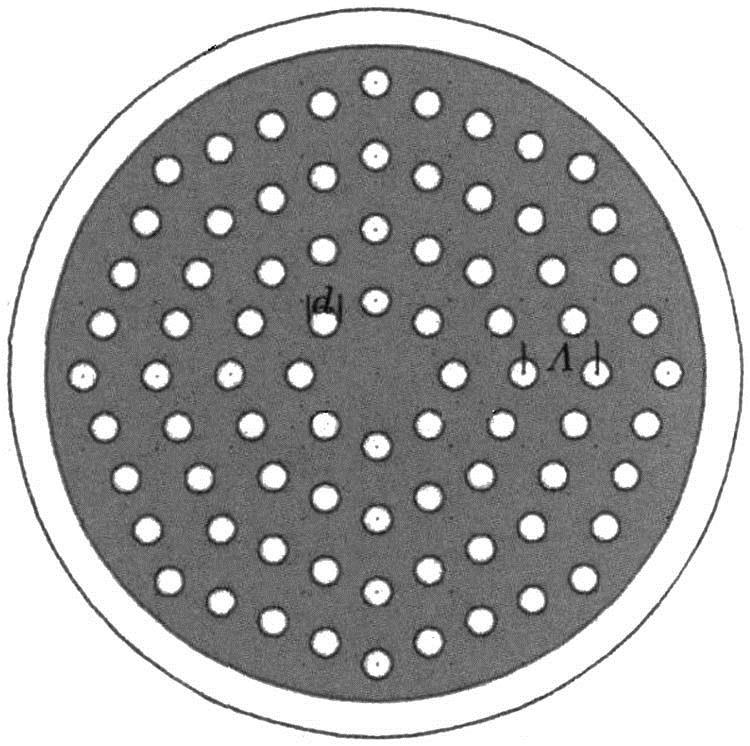
A photonic crystal fiber is divided into a total internal reflection photonic crystal fiber and a photonic bandgap of photonic crystal fiber. The core of the total internal reflection photonic crystal fiber is solid; the packet layer is a porous structure. The optical fiber used in this Letter is a total internal reflection photonic crystal fiber. Its section is shown in Fig. 1, which is composed of four layers of air hole octagonal distribution. is the air hole diameter, followed by from the inside out. is the hole pitch. The above five parameters are adjusted according to the design.
Changes of the ethanol refractive index coefficient with temperature are relatively large, so the four layers of the cladding holes are filled with liquid ethanol. The temperature coefficient of ethanol , while the temperature coefficient of quartz . The temperature coefficient of quartz is two orders of magnitude lower than the temperature coefficient of ethanol. Compared to ethanol, changes of the quartz refractive index can be ignored. The change of temperature will lead to changes in the alcohol refractive index and ultimately affect the change of the fiber effective area.
A schematic for the distributed temperature measurement is shown in Fig. 2. Using a photonic crystal fiber as the test optical fiber, the light from a distributed feedback laser diode light source is input to an electro-optic modulator for producing two first-order edge frequency light sources. The frequency interval is adjustable near the Brillouin frequency shift of the photonic crystal fiber.
Figure 2.Experimental facilities diagram of the distributed temperature measurement.
The pulse with a low frequency is converted to a recurrent pulse with a frequency of by a fast light door after reflecting via the narrowband Prague grating. Furthermore, the high-frequency light is amplified by a passed erbium-doped fiber and its optical power is controlled by the adjustable attenuator. Then it is converted into a pulse of width as a pump light through the fast light door. According to the length of the erbium-doped fiber, the time delay is controlled well, so the Stokes pulse will arrive at the other side of the test fiber earlier than the pump pulse, and then the SBS process will occur in the fiber from right to left. The probe pulse arrival time and power are measured with the digital oscilloscope. When the equipment works, the power of the received pulse sequence is judged first. If the power of the received pulse is higher than the power of the initial probe pulse, the pulse experiences the SBS process. Then the corresponding temperature can be calculated by the computer program on the basis of the pulse arrival time being determined by the temperature position or the pulses did not experience the SBS process. In other words, it does not contribute to the temperature measurement. Considering the SBS frequency shift changes slightly with temperature changes, when the range of the temperature change is very large, the best SBS process can be obtained by adjusting the input pump frequency, so the temperature distribution of the entire temperature range can be obtained.
For light propagating mainly in the fiber core, the core diameter is larger than the wavelength of light, the SBS-coupled amplitude equations of the ordinary single-mode fiber and approximation are also applied to the photonic crystal fiber with the total reflection of the structure, so the equations[12,13] are where are the amplitudes of the pump wave and Stokes wave, respectively; is the acoustic matter-density field; is the unperturbed density of the medium; is the group index of the fiber mode; is the velocity of the light in a vacuum; () is the loss (electrostriction) coefficient of the fiber; are the angular frequencies of pump wave (acoustic wave); is the full width at half maximum (FWHM) of the gain spectrum related to the phonon lifetime as , is the Brillouin frequency; and is the vacuum permittivity. We assumed that the + (−) z direction is the transmission direction of the Stokes wave (pump wave), where is the optical intensity of the pump (Stokes) wave; is the field distribution function of base mode in the fiber; is known as the effective mode area of the fiber; is the optical power of the pump (Stokes) wave.
In our numerical processing, applying the slowly-varying envelope approximation (SVEA) for both the pump and Stokes fields, first we obtained the values of at some time by solving Eq. (1c) with a Fourier transformation and an inverse Fourier transformation[14]. Second, we transform Eqs. (1a)–(1b) into single-variable partial differential equations by using characteristics. Finally, applying the value of we obtained to the single-variable partial differential equations, we can calculate the values of and at the next time by using the fourth-order Runge–Kutta formula. We set these results as the initialization value to achieve the value of at the next time. Repeating the above steps, we can achieve the output Stokes pulse at any time; thereby its power, time delay, and pulse broadening factor can be gotten[15], where the time delay, defined as , is the difference of the arrival time when the output Stokes pulse reaches its maximum between when the SBS happens and when SBS does not happen; the pulse broadening factor is defined as B, which is the proportion of the input Stokes pulse FWHM and output Stokes pulse FWHM.
, is the power of the output Stokes pulse at a high temperature and low temperature, respectively. () is the high (low) temperature. The temperature coefficient of the output relative power is defined as
For a photonic crystal fiber with the structure shown in Fig. 1, in order to obtain the largest variation of the effective area at the same temperature difference, after repeated numerical software calculations it is found that among all of the air holes the inner air holes have the biggest influence on thw effective fiber, so is the first to simulate it numerically from to . The result is that the variety of the fiber effective area with changes of temperature is the biggest when is . Similarly, are studied in turn. Finally, a set of parameters such as , , , and are chosen. The incident Stokes wavelength is 1.55 μm; the refraction rate of the core is 1.45; the refractive index of ethanol at 20°C is 1.36048. The effective area of the photonic crystal fiber at different temperatures was calculated by the software, as shown in Fig. 3. When the temperature is increased from 30°C to 70°C, the effective area of the fiber increased from 10.638 to 13.715, and at the higher temperature the effective area changed faster.
A continuous periodic signal is selected as the input Stokes pulse. The duty cycle is . In order to obtain a shorter delay and a smaller broadening factor, the pulse shape is super Gaussian and the parameter is set to 3[15]. Its FWHM is 10 ns, the period is 20 ns, and the peak power is 10 μW. The input pump is a single pulse with a super Gaussian shape, its FWHM is 10 ns, and the peak power is 1 W. Because the FWHM of the Stokes pulse is 10 ns, our spatial resolution can reach about 2 m. In order to improve the simulated accuracy of the time domain and space domain, the fiber length is set to 2.069 m. Under normal circumstances the time that light through a fiber with the length described above is 10 ns. When the temperature changes from 30°C to 70°C, the numerical calculation of the peak power of the output Stokes wave signal is shown in Fig. 4. The time delay and pulse broadening factor is shown in Fig. 5. The numerical computation accuracy on the time is 0.004 ns; the accuracy on the space is 0.8 mm. From Fig. 4 it can be found that when the temperature changes from 30°C to 70°C the power of the output Stokes pulse varies from 45.936 to 34.071 μW and the temperature coefficient of the output power is 0.00826. That is to say, in order to achieve the resolution of 1°C, the dynamic range of the power measurement equipment must be at least 42 dB, while the frequency detection experiments of spontaneous Brillouin scattering must be 80 dB. The main reason for such a remarkable difference is that the change of the fiber effective area leads to the change of light intensity, thus affecting the output Stokes power. From Fig. 5 it can be shown that the time delay and the pulse broadening factor change little with temperature. At the temperature range that is numerically calculated in this Letter, the time delay and pulse broadening factor only change by 0.08 ns and 0.019, respectively. This means that two adjacent pulses can be distinguished without any difficulty.
Figure 4.Output Stokes pulse power versus temperature.
The output power of a Stokes wave is calculated under ideal conditions, but the output power of a Stokes wave will be affected by various aspects. These effects will introduce large errors into our measurement system. Therefore, these effects must be considered in the system design. In order to decrease bending loss, the bending radius is increased as much as possible. In a given environment, the bending loss can be taken into account.Connection loss of various components can be corrected by the measurement of the actual instrument.Pump consumption. Because in our design there is only one pump pulse that interacts with a series of acoustic pulse fields and Stokes waves in the entire length of the fiber the pump energy will be part of the loss, which is not a constant value calculated in the simulation process. The following proposal is presented: for a very small loss per pump pulse cycle, the numerical simulation showed that when the fiber length is increased by about 200 m, the pump power will decline by 1%. So it can be ignored when the fiber length is short or, when conditions permit, the power of the Stokes pulse can be reduced and the power of the pump pulse can be improved. If a higher precision requirement is need, the influence of the pump power consumption will be taken into consideration in the numerical calculation progress.When the core diameter of the photonic crystal fiber is less than 1.55 μm, the SBS will present three Brillouin gain spectra with a several hundred MHz interval. The gain coefficient is less than for a conventional single-mode fiber. The effective area of the photonic crystal designed by us should not be too small, or in the process of measurement the frequency scanning range of the pump should be selected reasonably, because the temperature change of the fiber with 100°C range will lead to the Brillouin shift of about 120 MHz, which is less than the three gain spectral intervals.
In conclusion, it is found that the output power of the Stokes pulse can be used to transmit the temperature information with high resolution. Because of the limit in laboratory conditions, the related experiments fail to be carried out, and high precision of the optical power measurement is difficult. The actual system has some factors which will affect the output Stokes pulse power, such as the bending loss, the confinement loss, and the connection loss between different devices. However, most of the influencing factors can be solved by the correction based on the specific system. The calculation of the theory affirms the possibility that a photonic crystal fiber with liquid can be used as a distributed temperature sensor.
Yanyun Jin, Hongbing Li, Shanglin Hou, Ronghua Cui. Research on the temperature sensing mechanism of a photonic crystal fiber filled with liquid[J]. Chinese Optics Letters, 2015, 13(Suppl.): S20604