We present a novel homodyne frequency-shifting interference pattern locking system to enhance the exposure contrast of interference lithography and scanning beam interference lithography (SBIL). The novel interference pattern locking system employs a special homodyne redundant phase measurement interferometer (HRPMI) as the sensor and an acousto-opto modulator (AOM) as the actuator. The HRPMI offers the highly accurate value as well as the direction recognition of the interference pattern drift from four quadrature interference signals. The AOM provides a very fine resolution with a high speed for phase modulation. A compact and concise system with a short optical path can be achieved with this new scheme and a small power laser head in tens of microwatts is sufficient for exposure and phase locking, which results in a relatively low-cost system compared with the heterodyne system. More importantly, the accuracy of the system is at a high level as well as having robustness to environmental fluctuation. The experiment results show that the short-time (4 s) accuracy of the system is at present. Moreover, the phase of the interference pattern can also be set arbitrarily to any value with a high accuracy in a relatively large range, which indicates that the system can also be extended to the SBIL application.
A holographic diffraction grating with a subwavelength periodic structure is a widely used component in the field of optics. Recent studies[1–7] have been introduced to fabricate this type of diffraction grating. Holography exposure, or interference lithography (IL), is one of the frequently used methods[1,7]. During the holography exposure process, due to the index fluctuation, vibration, and thermal drift the relative movement between the interference pattern and substrate results in an exposure contrast loss. In order to maximize the exposure contrast, a feedback control system mainly made up of a phase measurement sensor and a phase modulation actuator, often named as the interference pattern locking or stabilizing system, is normally developed to depress the unwanted movement of the interference pattern.
In recent years, several interference pattern locking systems are proposed for IL in previous publications[1,2,5,6,7]. Heilmann et al.[2] introduced a digital heterodyne interference fringe control system that is made up of mainly three acousto-opto modulators (AOMs) and two heterodyne phase meters. It is an excellent system with a high interference pattern locking performance. However, the adopted three AOMs in this system must be used in series with a quite long optical path for heterodyne phase measuring and interference pattern phase shifting, which results in a large, complicated, and low power utilization system. Moreover, the system is also quite costly because of the expensive components and the ultraviolet (UV) laser head that is special for the heterodyne system. Schattenburg et al.[1] presented a system with two homodyne interference signals and an electronic-opto modulator (EOM). However, the accuracy of this system is relatively low due to the sensitivity of the homodyne interference signals to the fluctuation of the laser power and the disability of direction recognition of the interference pattern drift. In addition, the modulation range of the EOM is only about , which means that the system will be out of work when the phase variation of the interference pattern is larger than . Young et al.[7] provided an IL system with a CCD-PZT-based (PZT is lead zirconate titanate) feedback-locking function, where the overall IL device is very concise and the laser utilization is high. Nevertheless, the locking performance is very poor since the sample rate of the CCD sensor is merely 25 Hz and the PZT actuator is so slow that it would not be possible to control a disturbance with a frequency higher than 25 Hz. In addition, due to the environmental fluctuation between the measurement and exposure point, an environmental error exists in the above-mentioned systems[1,2,6,7]. Zeng et al.[5] proposed a latent-grating-based method for interference pattern drift measurement to eliminate the error. However, the exposure contrast can be damaged and the diffraction efficiency of the latent grating is very low, which also limits the application of this method. Therefore, the effective solution to reduce this drift error would be shortening the optical path and controlling the environment well between the measurement and exposure point.
In this Letter, we propose a novel interference pattern locking system with a specially-designed homodyne redundant phase measurement interferometer (HRPMI) as the sensor and an AOM as the actuator. The HRPMI offers the highly accurate value as well as the direction recognition of the interference pattern drift by four quadrature interference signals. As the HRPMI is very compact, the influence of the environmental fluctuation is much less and a high accuracy can be achieved even with less-tight environmental control. The AOM provides a very fine resolution with a high speed for phase modulation. With this new system scheme, both a compact and concise system with a short optical path can be achieved and a small power laser head on the level of tens of microwatts of power is sufficient for exposure and phase locking, which reduce the system cost compared with the heterodyne system. More importantly, the accuracy of the system and its robustness to environmental fluctuation are on a high level. The experiment demonstrated that the accuracy of the proposed system achieved . Moreover, the phase of the interference pattern can be locked to any arbitrary value with a high accuracy in a relatively large working range, which indicates that the system is suitable for scanning beam interference lithography (SBIL)[2] applications.
Sign up for Chinese Optics Letters TOC. Get the latest issue of Chinese Optics Letters delivered right to you!Sign up now
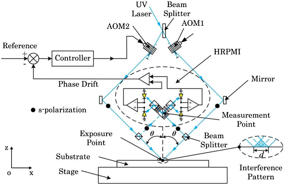
Figure 1 shows the schematic diagram of the homodyne frequency-shifting interference pattern locking system. The system is a traditional IL system that consists of two AOMs (AOM1, AOM2) and an HRPMI that are used to compensate the drift of the interference pattern. A continuous UV laser (, ) is divided into two beams by a beam splitter (BS), which then enter the two AOMs in the Bragg condition separately. Both AOMs are set to generate strong first-order diffracted beams with a frequency of (the value of is usually in hundreds of MHz), while the other weak orders of the diffracted beam are blocked. The driven frequency of AOM2 is always set as , while it can be changed around in a relatively small range to modulate the phase of the beam. Both first-order diffracted beams are projected onto the substrate at angle by the mirrors to form the interference pattern for exposure. In addition, an s-polarized laser is chosen to maximize the contrast of the interference pattern. During the exposure process, the interference pattern moves on the substrate because of the index fluctuation, vibration, and thermal drift. Close to the substrate, each beam is sampled by a weak BS. The two sampled beams enter the HRPMI, and then four interference signals with fixed phase shifts of 90° are formed. The four quadrature signals are transmitted to a computer. The value of the phase drift can be accurately calculated and the direction of the phase drift can be recognized by the four quadrature interference signals. The value of the phase drift of the interference pattern is fed back to the controller, and the AOM2 is ordered to shift the compensated phase to lock the interference pattern on the expected position on the substrate.
Figure 1.Schematic diagram of the novel homodyne frequency-shifting interference pattern locking system.
The theory of the system is explained by the formulas, as follows. The fields of the two interference beams are given by where is the amplitude of the electric field, and are the optical frequency of the first-order diffraction beam, is the value of the initial driven frequency of the AOMs, is optical path length, is the wavelength in air, is the wave number, and is the angle of incidence.
The intensity of the interference pattern at the substrate is expressed as where is the phase of the interference pattern and its expression is where is the optical path difference, and is the period of the interference pattern expressed as The phase of the interference pattern drifts during the exposure process and is caused by air index fluctuation, vibration, and thermal drift of the exposure beams; the variation can be derived from Eq. (4) as where is the variation of the wavelength and is the variation of OPD.
As shown in Fig. 1, due to the air index fluctuation between the exposure and measurement points, the value of the HRPMI as previously mentioned differs from the simultaneous phase drift of the interference pattern at the substrate. The drift of the interference pattern at the substrate is approximately measured by the HRPMI at the measurement point, and the value of the drift can be expressed as where is the value of the HRPMI. Thus, the locking accuracy of the interference pattern at the substrate will be reduced. The error caused by environmental fluctuation will be evaluated separately in the following section.
During the exposure process, the interference pattern moves on the substrate, then the phase drift is fed back to a controller to order the AOM2 shifts continuously with a frequency of ; the phase-shift value of the interference pattern can be expressed as where , is the value of the frequency variation of AOM2 and is the servo period of the control system.
When the drift and the shift of the interference pattern satisfies the interference pattern will be locked on the substrate.
The HRPMI shown in Fig. 1 is specially designed for the locking system that aims to offer the highly accurate value and direction recognition for the phase measurement of the interference pattern drift. The detailed scheme of the HRPMI used in the interference pattern locking system is shown in Fig. 2. The HRPMI is made up of a half-wave plate (HW), a BS, two polarized beam splitters (PBS), three quarter-wave plates (QWs), and four photodetectors (PDs). The angular position of the fast axis of the HW and QW is also indicated in Fig. 2. The two sampled beams with s polarization are divided into four sub-beams by the optics of the HRPMI. The phase and polarization of the sub-beams are controlled by the optics, and the intensities of four interference signals are formed at PD1, PD2, PD3, and PD4 with corresponding phase shifts of 0°, 90°, 180°, and 270°, respectively.
Figure 2.Detailed scheme of the homodyne redundant phase-measurement interferometer with four interference signals.
The intensities of four interference signals formed at PD1, PD2, PD3, and PD4 can be calculated with the Jones matrix of the optics, and the expressions are where is the DC amplitude and the AC amplitude of the ideal signal.
Furthermore, Eq. (10) can be written as
Finally, the phase can be derived from and as
It can be seen that the influence of is removed from and , which indicates that the accuracy of HRPMI is immune to the fluctuation of the laser power. In addition, the direction of the phase can also be determined from the quadrature signals and , which is a notable advantage of our system compared with the homodyne locking systems mentioned previously.
The experiment setup of the homodyne frequency-shifting interference pattern system was established as shown in Fig. 3 and mainly consists of an optical subsystem and a real-time VME (Versa Module Eurocard)-based control subsystem. The optical subsystem is mainly made up of two AOMs, an HRPMI, several mirrors, several beam splitters, and four PDs. Both of the AOMs are mounted at the Bragg angle with a driven frequency of 105 MHz to generate the maximum strong first-order diffracted beam for interference pattern exposure and locking. The HRPMI is designed by our group. The optics of the HRPMI is monolithically assembled on a mechanical mount while four fiber couplers are also inserted to transmit the optical interference signals to the PDs. A compact size of of the symmetric HRPMI can be achieved with this design, which greatly reduces the distance between the measurement and exposure point. It is a notable advantage of the system. The PD together with the amplifier transforms the optical interference signal to an electrical signal with a low signal-to-noise ratio for data acquisition. The PD is very sensitive to the beam with wavelength of 355 nm, which means that the requirement of the power for phase measurement is very low. The conversion gain of the HRPMI is 2.5 V/mW, which corresponds to a 0.4 mW input to each detector for 1 V standard voltage output. It is one of the key points to decreasing the requirement of the laser power for our system. According to the description above, a both compact and concise system with a high laser utilization and short optical path can be achieved based on our new scheme compared with the heterodyne system.
Figure 3.Photograph of experiment setup: (a) optics subsystem and (b) VME-based control subsystem.
The VME-based real-time control subsystem is made up of an A/D board (16 bits), a Power PC, a VME rack, a parallel I/O board, two frequency synthesizers with amplifiers, and a PC. The A/D board is used to acquire and subdivide the signals from the PDs with a low noise. The parallel I/O board outputs the control signal to the frequency synthesizer. The synthesizer and its amplifier provide driven signals for the AOMs, and both initial frequencies are set at 105 MHz. All boards are connected to the Power PC, and the Power PC is connected to a VME rack. The Power PC performs signals and control processing, which is programmed under the Tornado/VxWorks environment. The control software is developed under C++ compilers in a PC. The Power PC communicates with the PC by an Ethernet port and a Serial port. The resolution of the synthesizer is 0.233 Hz and the control frequency of our system achieves 5 kHz, which means that the interference pattern can be shifted continuously with a resolution of 0.0003 rad by the AOM2 according to Eq. (8). This is one of the key points for our system to achieve the high locking accuracy.
The errors of our system mainly involve HRPMI electronics error, HRPMI corrected residual error, environmental error, and control error. These errors will be analyzed in the following sections.
The total voltage noise of the PD together with the A/D board is about 1 mV, which corresponds to a phase noise of 0.0008 rad. Conventionally, the electronic error of HRPMI is 0.0008 rad .
In reality, the four interference signals expressed in Eq. (10), which is limited by the performance and alignment of the optics of the HRPMI, are unequal in amplitude and unquadrature in phase, which leads to periodic nonlinearity. Periodic nonlinearity is one of the main errors of the HRPMI and it can be corrected. In our system, a correction algorithm based on direct least-squares fitting of ellipses[8] is used to maximize the accuracy of the HRPMI. The algorithm is robust, efficient, and accurate and is suitable for the proposed real-time locking system.
An experiment is performed to verify the correction accuracy of the HRPMI. In this experiment, both initial frequencies of the two AOMs are set to 105 MHz, and an additional frequency of 8 Hz is added to AOM2. Therefore, an 8 Hz frequency difference is formed between the two interference beams. As a result, the value of the HRPMI will be increased in a slope with an ideal gradient of . The experiment data sets of the uncorrected and corrected signals and measurement value are acquired simultaneously, as shown in Fig. 4. Figure 4(a) shows the Lissajous curve of the signals from the HRPMI, and the value of the HRPMI is shown in Fig. 4(b). It can be seen that the HRPMI signals are greatly corrected. Figure 4(b) also indicates that the direction of phase can be recognized even if the value of the phase exceeds . However, a discrepancy exists between the real value and the ideal value, and it is influenced by the index fluctuation, vibration, and thermal drift of the beams as well as the nonlinearity of the HRPMI. The discrepancy and its amplitude spectrum density (ASD) in logarithmic coordinates are shown in Figs. 4(c) and 4(d), respectively. As the periodicity of the nonlinearity of the HRPMI is caused by nonideal signals, it can be separated from the total discrepancy in the ASD curve. The frequency and the ASD value of the periodic nonlinearity orders are also labeled in Fig. 4(d). As shown in the difference between the uncorrected (blue line) and corrected data (red line), the periodic nonlinearity of the HRPMI is greatly corrected with a residual error of 0.0008 rad, which is mainly limited by the noise of the HRPMI electronics.
Figure 4.Plots of uncorrected and corrected experiment data sets: (a) Lissajous curve of signals from the HRPMI, (b) value of the HRPMI, (c) discrepancy, and (d) ASD for the data from (c).
As shown in Fig. 1, due to the air index fluctuation between the exposure and measurement points, the value of the HRPMI differs from the phase drift of the interference pattern at the substrate, which also reduces the accuracy of the system. The error can be approximately calculated by where is the vacuum wavelength, is the variation of the refractive index of air, and is the optical path difference between the measurement and exposure points. The distance between the measurement and exposure points of our system is 50 mm, with a 5 mm optical path difference. According to Eq. (13), the environmental error of our system would be if the air index varies within , which requires for temperature, for pressure, for relative humidity, and 50 ppm for concentration stability between the measurement and exposure point. The air index variation is calculated according to the temperature, pressure, relative humidity, and fluctuation based on the Edlen equation latest modified by Birch and Downs at standard environmental parameters (T: 20°C, P: , RH: 40%, and : 365 ppm)[9]. Due to the compact and symmetric optical structure of the HRPMI, the environmental error is greatly reduced even with a loose environmental control compared with the heterodyne system. Therefore, our system is more robust to environmental fluctuation and the cost for a tight environmental control in a large volume is also cut down. This is a remarkable advantage of our system. The next step of our lab plan is to place an environmental enclosure with the above-mentioned parameter specification to ensure the accuracy of the system.
To verify the control performance of the proposed system, an experiment to control the interference pattern is performed with a PID algorithm, and an experiment without controlling is also performed for comparison. The control bandwidth and the setting time of the system are about 1360 Hz and 4.5 ms, respectively. In the experiment, both initial frequencies of the two AOMs are set to 105 MHz. The output of the HRPMI without controlling is illustrated in Fig. 5(a). Afterward, an order is input to the power PC to lock the interference pattern. The phase of interference pattern is locked instantly and remains stable at a fixed value with little variation, which is often called the control error. The value of the control error is illustrated in Fig. 5(b).
Figure 5.Experiment results: (a) interference pattern drift without locking, (b) residual drift with locking, and (c) ASD (in logarithmic coordinates) for the data from (a) and (b).
Figure 5(a) shows the uncontrolled value of the interference pattern drift in a conventional laboratory environment. It illustrates that the interference pattern drift varies about , which means that a complete loss of exposure contrast will occur if the exposure time is 4 s. Figure 5(b) shows the value of the residual error with controlling. The residual drift is obtained by subtracting the average phase value from the locking result, and its value is , which indicates that the proposed system can effectively lock the interference pattern on the substrate with high accuracy.
In order to get the frequency distribution of the drift and residual drift, the ASDs are calculated and their values are illustrated in Fig. 5(c), respectively. According to the ASDs in Fig. 5(c), the interference pattern drift is mainly caused by the low-frequency disturbances, and the drift caused by these low-frequency disturbances is greatly depressed by interference pattern locking. The control error below 194 Hz is , which reaches the accuracy limitation of our system. The control error mainly comes from the above 194 Hz disturbance frequency range with a total value of , and the control performance is mainly limited by the noise and delay of the electronics as well as the high-frequency vibration originating from the mechanical mounts. The next step of our plan is a new mechanical mount with high resonant frequency that will replace the current one to restrain the control error.
According to the analysis and experiment results above, the category and value of the errors of the proposed system are summarized in Table 1. These errors are dynamic errors in frequency domain, which contributes to a short-time error. The root sum square (RSS) of the total error of the system is .
The error caused by the thermal drift of the HRPMI is not listed in Table 1. The thermal drift of the optics and the mount of the HRPMI also leads to an error. This type of error is quasi-static, which contributes to a long-time error of the system. The current HRPMI is mainly made of aluminum, BK7, and crystalline quartz. A new HRPMI, which is mainly made of Zerodur material with a zero coefficient of thermal expansion, will be implemented to guarantee the long-time accuracy of the system.
In addition, in the SBIL[3] technology for a large grating fabrication application, the interference pattern locking system not only stabilizes the interference pattern but also simultaneously compensates the motion error of the substrate stage, which requires the system to be able to lock the arbitrary value of the interference pattern with high accuracy in a relatively large range. Our system also provides such a function to satisfy the requirement. In order to verify this function and its performance, an experiment is operated. In this experiment, all initial setup of the system is the same as mentioned above. An order to set the phase from 0 to with an interval of is input to the Power PC; the reference phase curve is shown in the red line in Fig. 6(a). In order to get an excellent locking result, anther PID parameter is applied, and the control bandwidth of the system is about 1210 Hz. The locking result is illustrated in the blue line in Fig. 6(a). The result shows that the phase of the interference pattern remains stable at 0, rad, rad, and rad. The overshoot is no more than 25.3% and the settling time is no more than 3 ms for the system when setting the phase as the red line in Fig. 6(a). The control errors are about , , , and , respectively, as shown in Fig. 6(b). The experiment result shows that the proposed system is also suitable for SBIL technology.
Figure 6.Experiment results: (a) locking result and (b) error.
In conclusion, we propose a novel interference pattern locking system with a special HRPMI as the sensor and an AOM as the actuator. With this configuration, a concise and low-cost system with a high accuracy is achieved. Moreover, the phase of the interference pattern can also be set arbitrarily to any value with a high accuracy in a relatively large range by the proposed system. In the future, the system will be used in an IL scanner being developed in Tsinghua to fabricate a large-size grating with a nanometer accuracy for ultra-precision displacement measurement applications[10].