• Chinese Journal of Lasers
  • Vol. 50, Issue 6, 0614001 (2023)
Zhongyang Li1、*, Qianze Yan1, Xinghai Chen2, Pibin Bing1, Sheng Yuan1, Kai Zhong3, and Jianquan Yao3
Author Affiliations
  • 1College of Electric Power, North China University of Water Resources and Electric Power, Zhengzhou 450045, Henan, China
  • 2Zolix Instruments Co. Ltd., Beijing 101102, China
  • 3College of Precision Instrument and Opto-Electronics Engineering, Institute of Laser and Opto-Electronics, Tianjin University, Tianjin 300072, China
  • show less
    DOI: 10.3788/CJL220656 Cite this Article Set citation alerts
    Zhongyang Li, Qianze Yan, Xinghai Chen, Pibin Bing, Sheng Yuan, Kai Zhong, Jianquan Yao. Investigation of EfficientTerahertz Wave Generation by Coupled Cascade Difference Frequency Generation[J]. Chinese Journal of Lasers, 2023, 50(6): 0614001 Copy Citation Text show less
    Schematics of CCDFG generating THz wave. (a) Schematic of photon interactions, where laser fill ratio indicates intensity of laser, red arrow indicates red-shifted process of cascaded optical difference frequency, and blue arrow indicates blue-shifted process of cascade optical difference frequency; (b) evolution of wave vectors; (c) schematic of experiment, where M1 and M2 can realize total reflection to dual idler waves, M3 can realize total reflection to dual idler waves and full transmission to dual signal wave, half wave plate changes dual idler waves from o-wave to e-wave, polarizer separates orthogonally polarized signal wave from idler wave, PE is polyethylene filter plate to filter out residual cascaded optical waves, and beam filter is used to remove residual pump waves
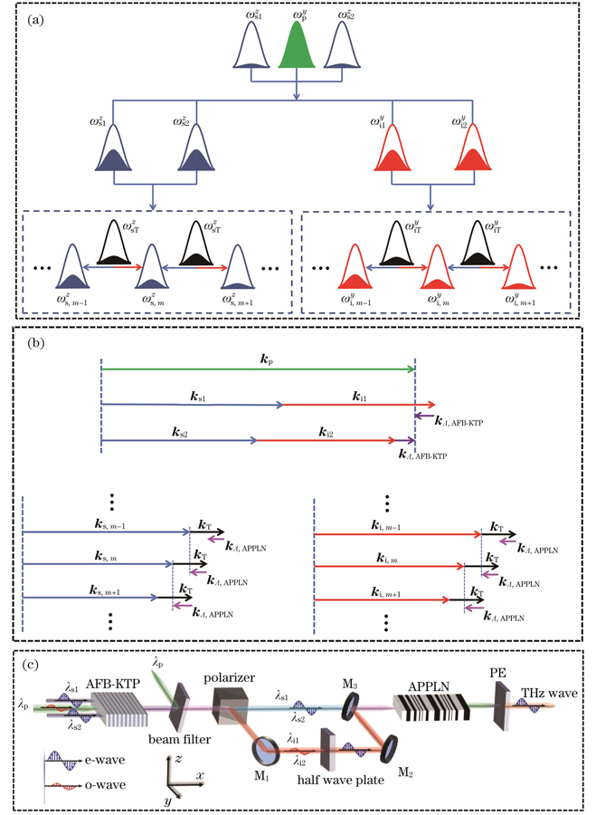
    Fig. 1. Schematics of CCDFG generating THz wave. (a) Schematic of photon interactions, where laser fill ratio indicates intensity of laser, red arrow indicates red-shifted process of cascaded optical difference frequency, and blue arrow indicates blue-shifted process of cascade optical difference frequency; (b) evolution of wave vectors; (c) schematic of experiment, where M1 and M2 can realize total reflection to dual idler waves, M3 can realize total reflection to dual idler waves and full transmission to dual signal wave, half wave plate changes dual idler waves from o-wave to e-wave, polarizer separates orthogonally polarized signal wave from idler wave, PE is polyethylene filter plate to filter out residual cascaded optical waves, and beam filter is used to remove residual pump waves
    At 300 K temperature, power density of pump wave, dual signal waves, and dual idle waves generated by coupled optical parametric amplification in AFB-KTP crystal (pump wavelength λp=532 nm, pump power density Ip=4000 MW/cm2, power density of seed ωs1z and ωs2z is 1/1019 of pump power density)
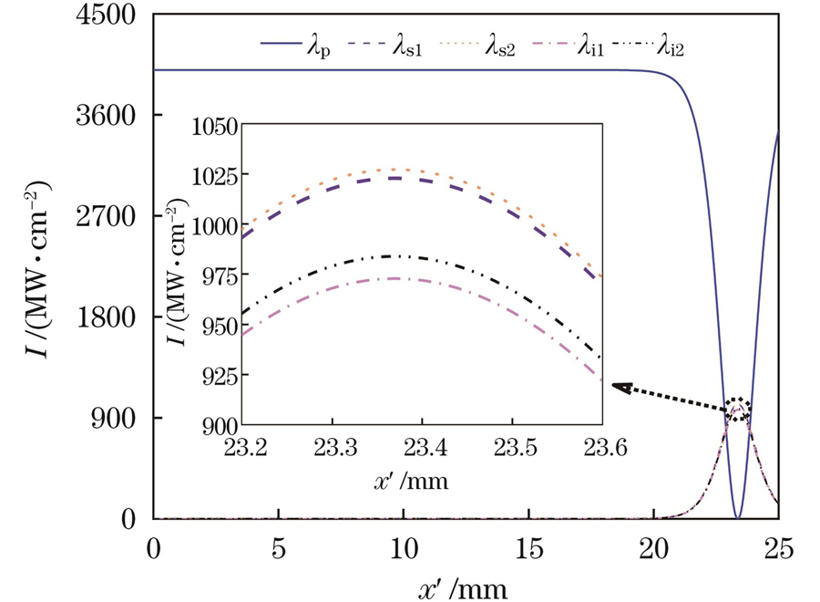
    Fig. 2. At 300 K temperature, power density of pump wave, dual signal waves, and dual idle waves generated by coupled optical parametric amplification in AFB-KTP crystal (pump wavelength λp=532 nm, pump power density Ip=4000 MW/cm2, power density of seed ωs1z and ωs2z is 1/1019 of pump power density)
    At 100 K temperature, CCDFG generates THz wave and cascaded optical waves, where power density of ωs1z and ωs2z is 1022.77 MW/cm2 and 1027.10 MW/cm2, respectively, and power density of ωi1z and ωi2z is 972.78 MW/cm2 and 983.85 MW/cm2, respectively. (a) Poling period versus crystal length; (b) phase mismatch distributions of each CDFG stimulated by dual signal waves; (c) phase mismatch distributions of each CDFG stimulated by dual idler waves; (d) evolution of THz wave, ωs,mz and ωi,mz generated by stimulating CCDFG with dual signal waves and dual idler waves, where Ic-s and Ic-i indicate the power density of ωs,mz and ωi,mz; (e) distribution of cascaded optical waves ωs,mz at crystal lengths x'= 0, 3.02, 5.00, 6.79, 7.95 mm; (f) distribution of cascaded optical waves ωi,mz at crystal lengths x'= 0, 3.02, 5.00, 6.79, 7.95 mm
    Fig. 3. At 100 K temperature, CCDFG generates THz wave and cascaded optical waves, where power density of ωs1z and ωs2z is 1022.77 MW/cm2 and 1027.10 MW/cm2, respectively, and power density of ωi1z and ωi2z is 972.78 MW/cm2 and 983.85 MW/cm2, respectively. (a) Poling period versus crystal length; (b) phase mismatch distributions of each CDFG stimulated by dual signal waves; (c) phase mismatch distributions of each CDFG stimulated by dual idler waves; (d) evolution of THz wave, ωs,mz and ωi,mz generated by stimulating CCDFG with dual signal waves and dual idler waves, where Ic-s and Ic-i indicate the power density of ωs,mz and ωi,mz; (e) distribution of cascaded optical waves ωs,mz at crystal lengths x'= 0, 3.02, 5.00, 6.79, 7.95 mm; (f) distribution of cascaded optical waves ωi,mz at crystal lengths x'= 0, 3.02, 5.00, 6.79, 7.95 mm
    At 100 K, evolution of THz wave and cascaded optical waves generated in CCDFG and CDFG, where Is1=1022.77 MW/cm2,Is2=1027.10 MW/cm2, Ii1=972.78 MW/cm2, Ii2 =983.85 MW/cm2. (a) Evolution of ωs,mz in CCDFG and CDFG, where Ic-s denotes power density of ωs,mz generated by stimulating CCDFG with dual signal waves and dual idler waves, Is denotes power density of ωs,mz generated by CDFG; (b) evolution of ωi,mz in CCDFG and CDFG, where Ic-i denotes power density of ωi,mz generated by stimulating CCDFG with dual signal waves and dual idler waves, and Ii denotes power density of ωi,mz generated by CDFG; (c) THz wave power density versus crystal length, where IT,c-s denotes power density of THz wave generated by CCDFG, IT,c-i denotes power density of THz wave generated by CCDFG, IT,s and IT,i denote power density of THz wave generated by stimulating CDFG with dual signal waves and dual idler waves, respectively
    Fig. 4. At 100 K, evolution of THz wave and cascaded optical waves generated in CCDFG and CDFG, where Is1=1022.77 MW/cm2,Is2=1027.10 MW/cm2, Ii1=972.78 MW/cm2, Ii2 =983.85 MW/cm2. (a) Evolution of ωs,mz in CCDFG and CDFG, where Ic-s denotes power density of ωs,mz generated by stimulating CCDFG with dual signal waves and dual idler waves, Is denotes power density of ωs,mz generated by CDFG; (b) evolution of ωi,mz in CCDFG and CDFG, where Ic-i denotes power density of ωi,mz generated by stimulating CCDFG with dual signal waves and dual idler waves, and Ii denotes power density of ωi,mz generated by CDFG; (c) THz wave power density versus crystal length, where IT,c-s denotes power density of THz wave generated by CCDFG, IT,c-i denotes power density of THz wave generated by CCDFG, IT,s and IT,i denote power density of THz wave generated by stimulating CDFG with dual signal waves and dual idler waves, respectively
    At 300 K temperature, CCDFG generates THz wave and cascaded optical waves, where power density of ωs1z and ωs2z is 1022.77 MW/cm2 and 1027.10 MW/cm2, respectively, and power density of ωi1z and ωi2z is 972.78 MW/cm2 and 983.85 MW/cm2. (a) Variation of poled period with crystal length; (b) phase mismatch distribution of each CDFG stimulated by dual signal waves; (c) phase mismatch distribution of each CDFG stimulated by dual idler waves; (d) evolution of THz wave, ωs,mz and ωi,mz generated by stimulating CCDFG with dual signal waves and dual idler waves; (e) distribution of cascaded optical waves ωs,mz at crystal length x'= 0, 2.28, 4.98, 5.56, 5.95 mm; (f) distribution of cascaded optical waves ωi,mz at crystal length x'= 0, 2.28, 4.98, 5.56, 5.95 mm
    Fig. 5. At 300 K temperature, CCDFG generates THz wave and cascaded optical waves, where power density of ωs1z and ωs2z is 1022.77 MW/cm2 and 1027.10 MW/cm2, respectively, and power density of ωi1z and ωi2z is 972.78 MW/cm2 and 983.85 MW/cm2. (a) Variation of poled period with crystal length; (b) phase mismatch distribution of each CDFG stimulated by dual signal waves; (c) phase mismatch distribution of each CDFG stimulated by dual idler waves; (d) evolution of THz wave, ωs,mz and ωi,mz generated by stimulating CCDFG with dual signal waves and dual idler waves; (e) distribution of cascaded optical waves ωs,mz at crystal length x'= 0, 2.28, 4.98, 5.56, 5.95 mm; (f) distribution of cascaded optical waves ωi,mz at crystal length x'= 0, 2.28, 4.98, 5.56, 5.95 mm
    At 300 K, evolution of THz wave and cascaded optical waves in CCDFG and CDFG, where Is1=1022.77 MW/cm2,Is2=1027.10 MW/cm2,Ii1=972.78 MW/cm2,Ii2=983.85 MW/cm2. (a) Evolution of ωs,mz in CCDFG and CDFG, where Ic-s denotes power density of ωs,mz generated by stimulating CCDFG with dual signal waves and dual idler waves, and Is denotes power density of ωs,mz generated by CDFG; (b) evolution of ωi,mz in CCDFG and CDFG, where Ic-i denotes power density of ωi,mz generated by stimulating CCDFG with dual signal waves and dual idler waves, Ii denotes power density of ωi,mz generated by CDFG; (c) THz wave power density versus crystal length
    Fig. 6. At 300 K, evolution of THz wave and cascaded optical waves in CCDFG and CDFG, where Is1=1022.77 MW/cm2,Is2=1027.10 MW/cm2,Ii1=972.78 MW/cm2,Ii2=983.85 MW/cm2. (a) Evolution of ωs,mz in CCDFG and CDFG, where Ic-s denotes power density of ωs,mz generated by stimulating CCDFG with dual signal waves and dual idler waves, and Is denotes power density of ωs,mz generated by CDFG; (b) evolution of ωi,mz in CCDFG and CDFG, where Ic-i denotes power density of ωi,mz generated by stimulating CCDFG with dual signal waves and dual idler waves, Ii denotes power density of ωi,mz generated by CDFG; (c) THz wave power density versus crystal length
    THz wave power density (IT,c-i) and energy conversion efficiency (η) generated by stimulating CCDFG at different pump power densities, where λp=532 nm, power density of seeds ωs1z and ωs2z is 1/1019 of pump wave power density
    Fig. 7. THz wave power density (IT,c-i) and energy conversion efficiency (η) generated by stimulating CCDFG at different pump power densities, where λp=532 nm, power density of seeds ωs1z and ωs2z is 1/1019 of pump wave power density
    Zhongyang Li, Qianze Yan, Xinghai Chen, Pibin Bing, Sheng Yuan, Kai Zhong, Jianquan Yao. Investigation of EfficientTerahertz Wave Generation by Coupled Cascade Difference Frequency Generation[J]. Chinese Journal of Lasers, 2023, 50(6): 0614001
    Download Citation