• Chinese Optics Letters
  • Vol. 13, Issue 5, 050603 (2015)
Fei Meng1、*, Zhongbao Qin1、3, Qiangzhou Rong2, Hao Sun2, Jiacheng Li2, Zaihang Yang2, Manli Hu2, and Honggao Geng1
Author Affiliations
  • 1Xi’an Research Institute of High-Technology, Xi’an 710025, China
  • 2Department of Physics, Northwest University, Xi’an 710069, China
  • 3e-mail: zhongb_qin@163.com
  • show less
    DOI: 10.3788/COL201513.050603 Cite this Article Set citation alerts
    Fei Meng, Zhongbao Qin, Qiangzhou Rong, Hao Sun, Jiacheng Li, Zaihang Yang, Manli Hu, Honggao Geng. Hybrid fiber interferometer for simultaneous measurement of displacement and temperature[J]. Chinese Optics Letters, 2015, 13(5): 050603 Copy Citation Text show less

    Abstract

    A hybrid fiber interferometer sensing configuration for displacement and temperature measurements is proposed and experimentally demonstrated that is constructed by splicing a short section of polarization maintaining optical fiber to an end-cleaved single mode optical fiber with a tapering structure. The reflected spectrum changes with the variation of displacement and temperature. The sensing configuration uses the method of wavelength and intensity modulations for displacement and temperature measurements, respectively, to which the sensitivities are 0.01392 nm/μm, 0.0214 dBm/μm, 0.09136 nm/°C, and 0.15795 dBm/°C. Experimental results show that displacement and temperature can be measured simultaneously by demodulating the reflected spectrum.

    Compared with conventional electrochemical sensors, all-fiber modal interferometer sensors have many outstanding advantages such as high sensitivities, light weight, high flexibility, good electromagnetic interference immunity, etc., which enable them to be applied in the detection of many ambient parameters, such as strain, pressure, displacement, curvature, temperature, refractive index, liquid level, etc. Extensive application prospects and excellent sensing performance make fiber interferometer sensors attractive to many researchers’ interests and thus lots of research results have been reported in recent years[111].

    Nowadays, the simultaneous measurement of parameters has become a hot research topic and our research group has already reported some research findings. In 2013, Zhang et al. reported an optical fiber sensor that used a Michelson fiber interferometer with a Hi-Bi fiber probe for the simultaneous measurement of refractive index and temperature[12]. In 2014, Sun et al. reported an optical fiber sensor based on a Mach–Zehnder interferometer (MZI), which is capable of the simultaneous measurement of temperature and strain or temperature and curvature[13].

    Displacement and temperature are significant parameters for various applications ranging from movement monitoring to industrial manufacture that should be monitored. So far, different types of optical fiber displacement sensors have been demonstrated by employing long-period gratings (LPGs)[14], fiber Bragg gratings (FBGs)[15], a MZI[16] and a Sagnac interferometer[17]. However, temperature monitoring is of great importance for accurate displacement measurement due to the issue of temperature cross-sensitivity. In order to solve this problem, simultaneous measurement of displacement and temperature has been studied. The measuring method of using a fiber Bragg grating cladding mode based on core diameter mismatch was reported by Rong et al. in 2012[18]. An optical fiber sensor based on a thin core fiber has been proposed and experimentally demonstrated for the simultaneous measurement of displacement and temperature by Wu et al. in 2014. This thin-core fiber modal interferometer obtained the displacement and temperature sensitivities of 0.01028nm/μm, 0.01535nm/μm, 0.00942 nm/°C, and 0.00493 nm/°C[19]. It is necessary to improve the measurement precision through the simultaneous measurement of displacement and temperature.

    In this Letter, we present a hybrid fiber interferometer for the simultaneous measurement of displacement and temperature based on polarization maintaining fiber (PMF). The proposed device is fabricated by splicing a short section of PMF to an end-cleaved single mode fiber (SMF), which has a conical structure. Since the reflected spectrum has different responses to external displacement and temperature perturbations, a sensing matrix can be obtained from the experiment and the displacement and temperature variation can be calculated after measuring the reflected interference spectrum. In this way, the cross-sensitivity issue is eliminated. It is possible to achieve the simultaneous measurement of displacement and temperature. For this proposed device, which has a small size, stable structure, and high measurement accuracy, just one sensor can realize double parameter measurement and meet the demand of applications.

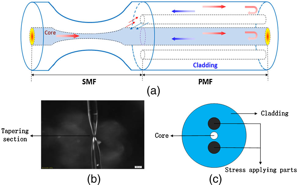
    The schematic diagram of the proposed sensor is shown in Fig. 1(a). The total length of the sensing head is about 40 mm. SMF is used for making the tapering structure with a commercial fusion splicer (Fujikura FSM-60S) under the manual operation mode. The core/cladding diameter of the SMF used in the experiment is 9/125 μm. The length of the tapering structure is 526 μm and the diameter of the waist is 40 μm, according to the optical microscope image shown in Fig. 1(b). A section of PMF with a length of 30 mm is spliced to the tapering structure at a distance of 8 mm from the waist. The PMF used in the experiment is a type of PM1550 and the mode field diameter is 9.8 μm. The structure of the PMF is shown in Fig. 1(c). This design of the reflective structure is more convenient for measurement.

    (a) Schematic diagram of the sensor; (b) microscopic image of the tapering structure; (c) the structure of the PANDA PMF.

    Figure 1.(a) Schematic diagram of the sensor; (b) microscopic image of the tapering structure; (c) the structure of the PANDA PMF.

    When the input light propagates through the tapering section of the SMF, a multitude of cladding modes are excited in the PMF due to the mode field mismatch. Both the core mode and the cladding modepropagate along the PMF and part of them is reflected by the end face of the PMF. The reflected cladding mode interferes with the reflected core mode when the light is recoupled back to the tapering section. For the modal interferometer, the phase difference ϕm between the core modes and the cladding modes can be written as[20]ϕm=4πΔneffLλ,where Δneff is the effective index difference between the core and cladding modes, L is the length of the PMF, and λ is the central wavelength of the input light. When the phase difference ϕm=(2m+1)π, where m is a positive integer, the interference light intensity will reach its minimum and the notch wavelength can be expressed as[20]λm=4πΔneffL(2m+1)π.

    By applying displacement variations through bending the sensor, the effective cladding mode indices will change accordingly, while the core mode index is generally maintained because the core diameter is much smaller than that of the cladding and the length of the sensor has little influence on the large bent radius[21,22]. The dip wavelength shift due to the displacement increment can be described as δλm=4(Δneffδn)L2m+14ΔneffL2m+1=4δnL2m+1,where δn is the change of Δneff caused by the displacement variations.

    Both the core and cladding mode effective refractive indices change with the increase of environmental temperature while the effective refractive index of the core mode varies more than the cladding mode due to the different thermal-optic coefficients of the core and cladding material and the length of the PMF also changes due to the thermal expansion effect. The temperature sensitivity of the sensor can be derived as[23]dλmdT[4L2m+1(ΔneffncodncodT+ΔneffncldncldT)+4Δneff2m+1dLdT]14L2m+1Δneffλ,where Δneff=nconcl, nco, and ncl are the effective refractive indices of the core and cladding modes.

    Furthermore, for the interferometer, the reflected spectral intensity I can be written as[20]I=Ico+Icl+2IcoIclcos(ϕm),where Ico and Icl are the intensities of the core and cladding modes reflecting from the interferometer. The phase difference ϕm will be changed with the displacement or temperature variations, which causes the change of Δneff, and then the variety of the reflected spectral intensity is brought about. Thus, the measurement of displacement or temperature can be achieved through measuring the reflected spectral intensity.

    When the input light is linearly polarized, except for the interference between the cladding mode and core mode, it will cause polarization interference at the same time. The reflected spectrum of the sensor is superimposed by the two kinds of interference.

    The schematic diagram of the experimental setup is shown in Fig. 2. Light from the amplified spontaneous emission (ASE) source passes through the circulator, polarizer, and polarization controller, and then launched into the sensor. In the process of the experiment, the sensor is fixed on two opposite parallel platforms. The relative position of the two platforms is changed by moving one of them. Then the change of displacement that causes a microbend of the sensor can be measured by the experimental setup. Different displacements can be achieved by moving the platform to the left or right, and the magnitude of the displacement can be read from the micrometric screw on the platform. Through the output port of the circulator, the reflected interference spectrum is monitored by an optical spectrum analyzer (OSA) with a resolution of 0.02 nm/0.01 dB. An ideal interference spectrum can be obtained by adjusting the polarization controller. The different polarization states of input light can only lead to the different characteristic peaks, but cannot affect the experimental results. Therefore, we can use the interference spectrum for measurement.

    Schematic diagram of the experimental setup for the displacement measurement.

    Figure 2.Schematic diagram of the experimental setup for the displacement measurement.

    The reflected interference spectrum and the response of dip A have been analyzed. The corresponding spectral responses to different displacements are shown in Fig. 3.

    Reflected interference spectrum and reflection spectra of dip A for different displacements.

    Figure 3.Reflected interference spectrum and reflection spectra of dip A for different displacements.

    It is apparent that the interference fringes shift and the intensity of the peak changes as the displacement increases from 0 to 350 μm with a step of 50 μm. With the displacement increasing, dip A exhibits a redshift and intensity increase. The relationships between the displacement and wavelength (intensity) of dip A are plotted in Figs. 4 and 5, respectively. The response of dip A to the displacement variations demonstrates good linearity and the linear with linear correlation coefficients of larger than 0.99. The linear fitting functions for the wavelength and intensity are Y=1561.26379+0.01392X and Y=57.57583+0.0214X, respectively.

    Wavelength shifts as a function of displacement for dip A.

    Figure 4.Wavelength shifts as a function of displacement for dip A.

    Intensity changes as a function of displacement for dip A.

    Figure 5.Intensity changes as a function of displacement for dip A.

    The schematic diagram of the experimental setup is shown in Fig. 6. A temperature controlled oven with a temperature error of ±0.1°C and temperature fluctuation of 1% was used for the temperature experiment. In order to eliminate the influence of the temperature fluctuation during the measurement process, the temperature was kept constant for 30 min to ensure a well-distributed temperature value in the oven before each record.

    Schematic diagram of the experimental setup for the temperature measurement.

    Figure 6.Schematic diagram of the experimental setup for the temperature measurement.

    The reflected interference spectrum and the response of dip A have been analyzed. The corresponding spectral responses to different temperatures are shown in Fig. 7. It can be seen from Fig. 7 that dip A shows a blueshift and an intensity increase as the temperature increases from 25 to 60°C with a step of 5°C.

    Reflection spectra of dip A for different temperatures.

    Figure 7.Reflection spectra of dip A for different temperatures.

    From Figs. 8 and 9, the temperature sensitivities of 0.09136nm/°C and 0.15795 dBm/°C can be obtained based on linear fitting of the temperature response.

    Wavelength shifts as a function of temperature for dip A.

    Figure 8.Wavelength shifts as a function of temperature for dip A.

    Intensity changes as a function of temperature for dip A.

    Figure 9.Intensity changes as a function of temperature for dip A.

    It can be seen that the respective displacement sensitivities of dip A that are based on the demodulation of the wavelength and intensity are 0.01392 nm/μm and 0.0214 dBm/μm, and the corresponding temperature sensitivities are 0.09136nm/°C and 0.15795 dBm/°C. Based on the experimentally acquired displacement and temperature sensitivities, a sensing matrix can be given by [ΔλΔP]=[KλDKλTKPDKPT][ΔDΔT]=[0.013920.091360.02140.15795][ΔDΔT],where Δλ and ΔP respectively refer to the wavelength shift and intensity change of dip A, and ΔD and ΔT are the variations of displacement and temperature, respectively.

    From Eq. (6), a new matrix can be written as [ΔDΔT]=[0.013920.091360.02140.15795]1[ΔλΔP].

    According to Eq. (7), the displacement and temperature variation can be calculated after measuring the wavelength shift and intensity change. Consequently, for this proposed sensing device, the simultaneous measurement of displacement and temperature can be realized through the demodulation matrix.

    In conclusion, we propose and demonstrate a hybrid fiber interferometer sensing configuration for the simultaneous measurement of displacement and temperature. The sensor is constructed by splicing a short section of PMF to an end-cleaved SMF, which has a tapering structure. The displacement sensitivities reach 0.01392 nm/μm and 0.0214 dBm/μm within a displacement range of 0–350 μm, and the temperature sensitivities are 0.09136nm/°C and 0.15795 dBm/°C for a temperature range of 25–60°C. The wavelength resolution of the OSA is 0.02 nm, so the displacement and temperature resolutions of the sensor are 1.44 μm and 0.22°C. The simultaneous measurement of displacement and temperature can be realized through the demodulation matrix. Owing to its advantages of dual parameter simultaneous measurement, simple structure, measurement accuracy, compact size, ease of fabrication, and good electromagnetic interference immunity, the proposed sensor has potential applications in structural health monitoring and real-time damage identification applications.

    References

    [1] S. Yang, H. Sun, L. Yuan, X. Zhang, L. Zhou, M. Hu. Chin. Opt. Lett., 11, 120604(2013).

    [2] J. Yang, J. Huang, X. Li, S. Li, B. Luo, C. Tao, W. Chen. Chin. Opt. Lett., 11, 080601(2013).

    [3] Q. Rong, X. Qiao, R. Wang, H. Sun, M. Hu, Z. Feng. IEEE Sens. J., 12, 2501(2012).

    [4] Q. Rong, H. Sun, X. Qiao, J. Zhang, M. Hu, Z. Feng. J. Opt., 14, 045002(2012).

    [5] C. Wu, H. Y. Fu, K. K. Qureshi, B. O. Guan, H. Y. Tam. Opt. Lett., 36, 412(2011).

    [6] J. Wang, B. Dong, E. Lally, J. Gong, M. Han, A. Wang. Opt. Lett., 35, 619(2010).

    [7] J. Zhang, H. Sun, Q. Rong, Y. Ma, L. Liang, Q. Xu, P. Zhao, Z. Feng, M. Hu, X. Qiao. Chin. Opt. Lett., 10, 070607(2012).

    [8] H. Liu, W. Wang, X. Li, F. Gao. Chin. Opt. Lett., 11, 101501(2013).

    [9] Y. Deng, M. Li, N. Huang, H. Wang, N. Zhu. Photon. Res., 2, B35(2014).

    [10] Y. E. Fan, T. Zhu, D. W. Duan, Y. J. Rao. J. Optoelectron. Laser, 21, 15(2010).

    [11] H. F. Song, H. P. Gong, K. Ni, X. Y. Dong. J. Optoelectron. Laser, 24, 1082(2013).

    [12] J. Zhang, H. Sun, R. Wang, D. Su, T. Guo, Z. Feng, M. Hu, X. Qiao. IEEE Sens. J., 13, 2061(2012).

    [13] H. Sun, S. Yang, X. Zhang, L. Yuan, Z. Yang, M. Hu. Opt. Commun., 340, 39(2015).

    [14] L. Qi, C. L. Zhao, Y. Wang, J. Kang, Z. Zhang, S. Jin. Opt. Express, 21, 3193(2013).

    [15] C. Shen, C. Zhong. Sens. Actuators A, 170, 51(2011).

    [16] C. Zhong, C. Shen, Y. You, J. Chu, X. Zou, X. Dong, Y. Jin, J. Wang. J. Opt. Soc. Am. B, 29, 1136(2012).

    [17] M. Bravo, A. M. R. Pinto, M. Lopez-Amo, J. Kobelke, K. Schuster. Opt. Lett., 37, 202(2012).

    [18] Q. Rong, X. Qiao, J. Zhang, R. Wang, M. Hu, Z. Feng. J. Lightwave Technol., 30, 1645(2012).

    [19] J. Wu, Y. Miao, B. Song, W. Lin, K. Zhang, H. Zhang, B. Liu, J. Yao. Opt. Commun., 340, 136(2014).

    [20] L. Li, L. Xia, Z. Xie, L. Hao, B. Shuai, D. Liu. Sens. Actuators A, 180, 19(2012).

    [21] J. Chen, J. Zhou, Z. Jia. IEEE Photon. Technol. Lett., 25, 2354(2013).

    [22] J. Chen, J. Zhou, X. Yuan. IEEE Photon. Technol. Lett., 26, 837(2014).

    [23] B. Gu, M. Yin, A. P. Zhang, J. Qian, S. He. Opt. Express, 17, 22296(2009).

    Fei Meng, Zhongbao Qin, Qiangzhou Rong, Hao Sun, Jiacheng Li, Zaihang Yang, Manli Hu, Honggao Geng. Hybrid fiber interferometer for simultaneous measurement of displacement and temperature[J]. Chinese Optics Letters, 2015, 13(5): 050603
    Download Citation