
W. P. Wang, X. M. Zhang, X. F. Wang, X. Y. Zhao, J. C. Xu, Y. H. Yu, L. Q. Yi, Y. Shi, L. G. Zhang, T. J. Xu, C. Liu, Z. K. Pei, and B. F. Shen. Ion motion effects on the generation of short-cycle relativistic laser pulses during radiation pressure acceleration[J]. High Power Laser Science and Engineering, 2014, 2(2): 020000e9
- High Power Laser Science and Engineering
- Vol. 2, Issue 2, 020000e9 (2014)
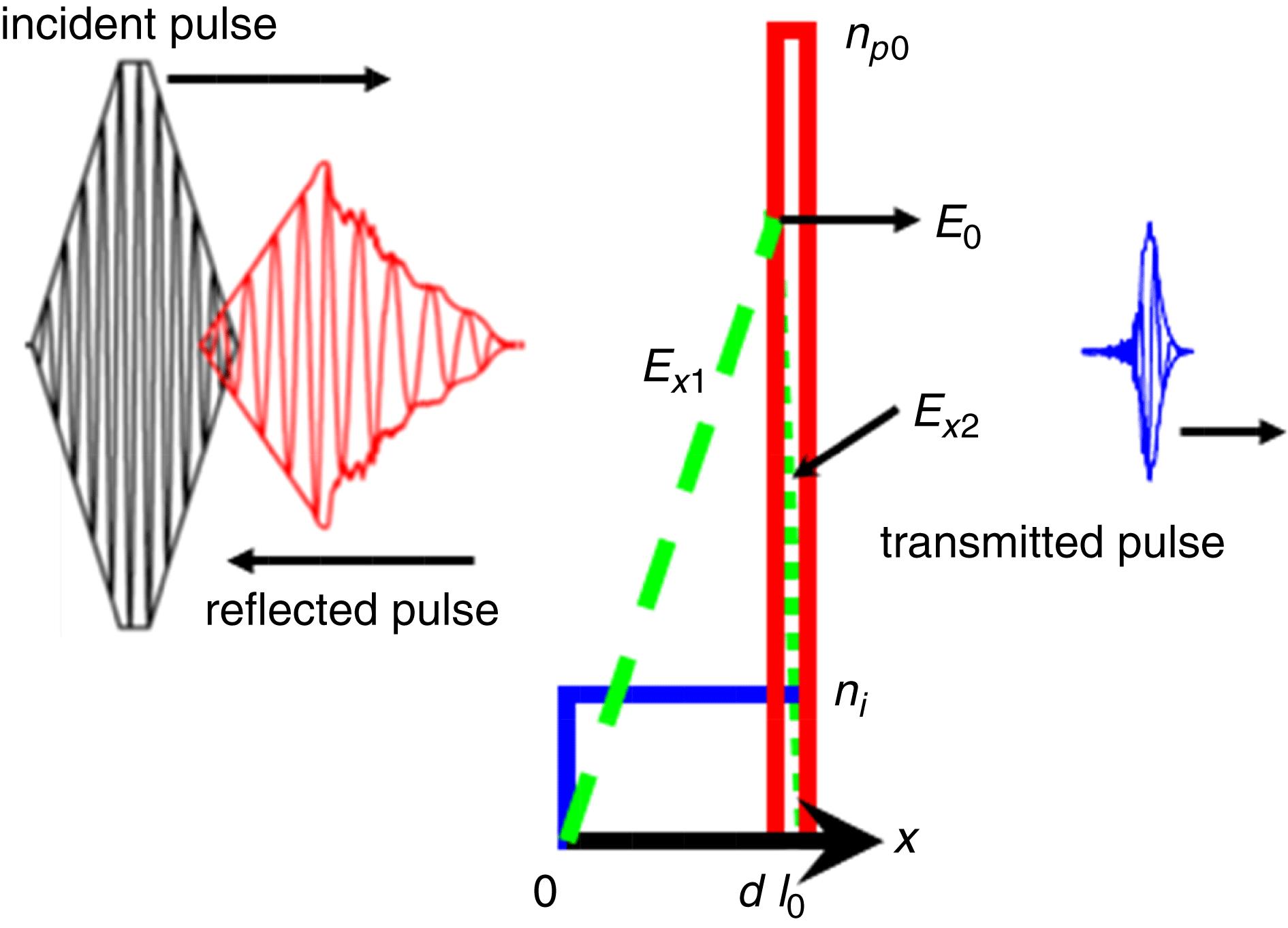
Fig. 1. Scheme for generating nearly single-cycle laser pulses. The incident pulse irradiates a thin foil, producing an ultra-short transmitted pulse and a reflected pulse. Electrostatic fields  (green dashed line) and
  (green dotted line) are produced at both sides of the surface (at
  ) of the CEL (red solid line) at the initial stage of the interaction. Ions (blue solid line) remain at rest. The distribution of the electrons corresponds to the case where the CEL just reaches the back side of the target. The CEL then oscillates and disperses, as shown in Figures
 2 c and 2 d.
(green dashed line) and (green dotted line) are produced at both sides of the surface (at ) of the CEL (red solid line) at the initial stage of the interaction. Ions (blue solid line) remain at rest. The distribution of the electrons corresponds to the case where the CEL just reaches the back side of the target. The CEL then oscillates and disperses, as shown in Figures 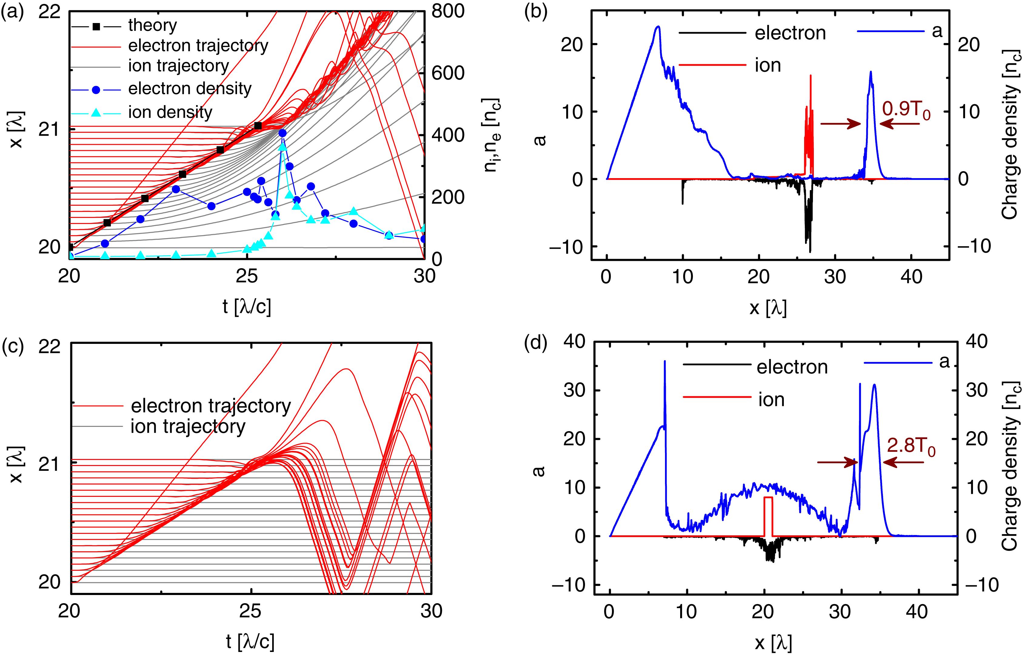
Fig. 2. 1D PIC simulation results for  (
( and
and  ),
),  , and
, and  . (a) Electron and proton trajectories and their density peaks versus time. (b) Laser profile (blue solid line) and charge density of electrons (black solid line) and ions (red solid line) at
  for the case of moving ions. (c) Electron and proton trajectories and (d) laser profile (blue solid line) and charge density of electrons (black solid line) and ions (red solid line) at
  for the case of ions at rest.
( and ), , and . (a) Electron and proton trajectories and their density peaks versus time. (b) Laser profile (blue solid line) and charge density of electrons (black solid line) and ions (red solid line) at for the case of moving ions. (c) Electron and proton trajectories and (d) laser profile (blue solid line) and charge density of electrons (black solid line) and ions (red solid line) at for the case of ions at rest. Fig. 3. (a) Amplitude peak  (black square) and duration (blue triangle) of transmitted pulses versus foil thickness
  . For the incident laser,
  (
( and
and  ). The foil density is
  . Laser profile (blue solid line) and charge density of electrons (black solid line) and ions (red solid line) for
  (
( and
and  ) and (b)
  , (c)
, (c)  .
.
(black square) and duration (blue triangle) of transmitted pulses versus foil thickness . For the incident laser, ( and ). The foil density is . Laser profile (blue solid line) and charge density of electrons (black solid line) and ions (red solid line) for ( and ) and (b) , (c) . Fig. 4. Laser profile  (blue solid line) and charge density of electrons (black solid line) and
  ions (red solid line) for
  (
( and
and  ). The foil density is
  , and the foil thickness is
  .
.
(blue solid line) and charge density of electrons (black solid line) and ions (red solid line) for ( and ). The foil density is , and the foil thickness is . Fig. 5. Electron (red circle) and ion (blue circle) distribution and the laser profiles in the ( ,
,  ) plane for foils with
  and
and  irradiated by CP laser pulses with
  (
( and
and  ) at
) at  . The axial laser profiles at
  are denoted by the black solid lines.
, ) plane for foils with and irradiated by CP laser pulses with ( and ) at . The axial laser profiles at are denoted by the black solid lines. 
Set citation alerts for the article
Please enter your email address
© Copyright 2018-2021 | Chinese Laser Press. All Rights Reserved 沪ICP备15018463号-20