Mingliang Long, Meng Chen, Gang Li, "Six 38.7 W pulses in a burst of pulse-burst picosecond 1064 nm laser system at 1 kHz," Chin. Opt. Lett. 15, 021403 (2017)
Copy Citation Text
A burst of six pulses with an average power of 38.7 W are obtained for a pulse-burst picosecond 1064 nm laser system at 1 kHz. The six pulses have equal amplitudes and pulse spacings of 800 ps, the beam quality of the factor is less than 2, and the pulse width is 67 ps. Seed pulses are broadened from 22 to 136 ps by single-pass volume Bragg gratings. A laser-diode end-pump beam-splitting amplifier is used to divide and amplify a single pulse into six pulses. An Nd:YAG regenerative amplifier and a single-pass high-gain amplifier are applied.
Ultrashort pulse-burst picosecond lasers have been widely used in the production of equipment for x rays, industrial processing, communications engineering, biology sciences, and other fields[1–9]. High-energy pulse-burst picosecond lasers with a narrow pulse spacing are good x ray spectrum transform pump sources[1–3]. When using a multipass Yb:KYW amplifier, each burst contains 100 pulses totaling 20 mJ of energy at a pulse repetition frequency (PRF) of 1 kHz, a flux of in a 5% bandwidth, a brilliance of , and a pulse duration of 0.5 ps for a compact x ray light source was achieved[1]. A single 100 ps, 1.053 μm wavelength pulse from a Kuizenga-type oscillator was divided into eight equal-intensity pulses using a set of beam splitters and mirrors. The peak-to-peak time interval between each pulse was fixed at 250 ps. When it was irradiated on an aluminum slab target at a peak pump intensity of , a time-integrated small signal gain coefficient of was observed at 300 μm from the target surface for a 154.7 Å Li-like Al laser, and the effective ablation rate was calculated to be /min[2]. Manufacturing processes using picosecond lasers generate less heat and have high precision, so they are applied in the manufacturing of several materials and are commonly used in micro and nanoprocessing[4,5]. A pulse burst can effectively reduce the threshold and improve the processing speed, so it has a better effect compared to a single pulse. In processing of steel, silicon, and tungsten carbide, the use of pulse bursts with 10 pulses at high PRFs has been shown to be 15 times faster compared to single pulses at low PRFs with the same average power[4]. In addition, pulse-burst picosecond lasers are very beneficial in the processing of diamonds and other gems[6,7]. High-power pulse-burst picosecond lasers are often easier to obtain than single picosecond laser pulses, and hence, they are more widely applied in many fields. Thus, pulse-burst picosecond lasers with a higher power and a narrower pulse spacing would be advantageous to the development of related research and commercialization. Pulse bursts can be obtained using several methods. One method is to use a Michelson interferometer to obtain pulse bursts for splitting and combining pulse beams. Split beams have a different optical path before they combine, so when they are combined into one beam, there will be multiple pulses at the same moment[10–12]. In 1998, a femtosecond laser with a single pulse energy of 1 mJ and a pulse width of 150 fs was divided into 16 roots at a PRF of 1 kHz[12]. Since the speed of light is faster, the geometric space would be much larger for this. An optical switch device was another method for choosing pulse bursts with high PRFs[4,5]. In terms of precision processing, Nebel et al.[5] reported a single pulse energy of 100 nJ for pulse bursts of 2, 10, and 20 pulses by controlling the high voltage of Pockels cells (PCs). Owing to limitation of the response time of high voltage optical switch-offs, the pulse spacing was mostly more than nanoseconds. An electro-optic -switch was applied by Bai et al.[13] to select five pulses in a burst at a PRF of 1 kHz, and gratings were used to stretch the seed pulses from 8.5 to 99.9 ps through regenerative amplifier (RA) and a compressor. An envelope energy of 14 mJ was obtained in an envelope containing five pulses. Femtosecond pulse bursts can also be produced using birefringent crystals. When an optical beam is injected into a birefringent crystal, it is split into two polarized beams (o- and e-optical beams). Since the two refractive indexes of light in the crystal are not the same, the optical paths of the split beams would be different, thus separating one pulse into two or more pulses. A picosecond-spaced pulse train suitable for coherent terahertz production has been realized by using four pieces of -BBO crystals to separate an input UV pulse with the appropriate duration into 16 sub-pulses[14]. However, the difference between the two refractive indexes of light in the birefringent crystals was not very large, and hence, the spacing of the multiple pulses was generally around a few picoseconds. Generally, the pulse energy in bursts decreases gradually in picosecond pulse-burst lasers. In this Letter, a single pulse was split into a burst and amplified by a laser-diode (LD) end-pump beam-splitting amplifier (LPBSA). There was narrow spacing between each pulse in the burst. By changing the angle of the quarter-wave plate (QWP) and the strength of the LD pump width, the pulse amplitude and numbers were varied. At the same time, the pulse spacing could be controlled by adjusting the lengths of and in the LPBSA.
In recent years, new kinds of Bragg diffraction gratings with a high damage threshold, namely, volume Bragg gratings (VBGs) or chirped VBGs, have been developed using a photo-thermo refractive glass, and its performance has been reported to be good for picosecond pulse broadening and compression[15,16]. In this Letter, the seed pulse was subjected to a single pass through the VBG, and its pulse width was broadened to 136 ps. Finally, we obtained six pulses with an average power of 38.7 W in a pulse-burst picosecond laser system at a PRF of 1 kHz. The six pulses in the burst had an equal amplitude and pulse spacing. The spacing between each pulse was 800 ps, the PRF was up to gigahertz, and the beam quality of the factor was less than 2. The pulse width was self-compressed to 67 ps, the stability for the power root-mean-square (rms) was less than 3%, and the beam pointing was approximately 40 μrad. The structure was simple, and the total footprint of the laser system was less than 0.4 m2.
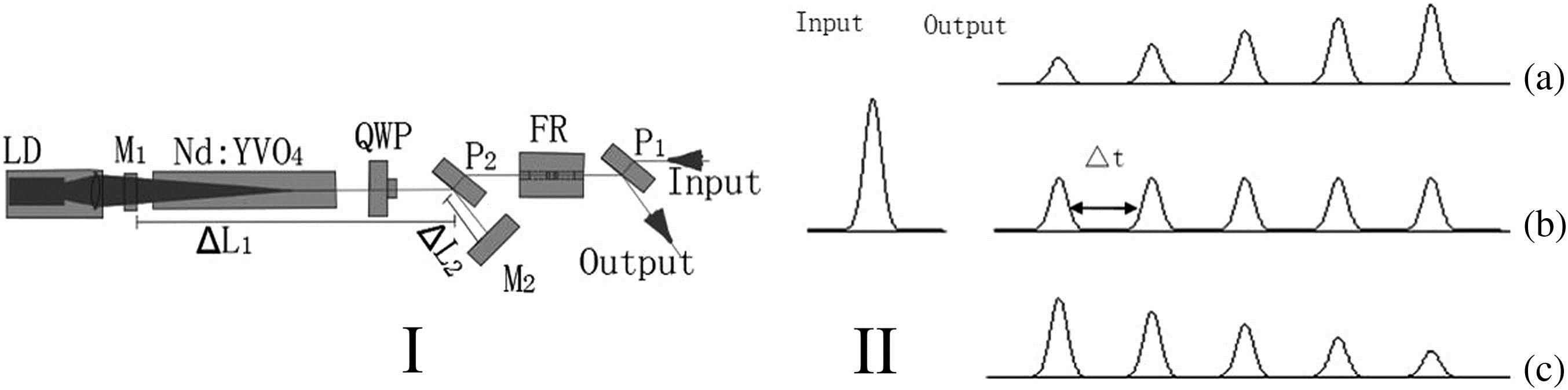
Figure 1 shows the structure of the LPBSA. The crystal was 0.6% doped and had dimensions of . The pump surface of the crystal had an antireflection coating at 808 nm and a high-reflection coating at 1064 nm. The other side had an antireflection coating at 1064 nm. A single pulse passed through a thin polarizing film (P1), a Faraday isolator (FR), a thin polarizing film (P2), a QWP, and a quasi-continuous pump end-pumped amplifier module. It is reflected by the end of the and passed through the QWP again. A part of the beam travels through P2 and P1, and the first pulse in a burst was formed. The other part was reflected by P2 to a 0° reflective mirror (M2), and it was completely reflected on the original path. Thus, pulses in a burst with a narrow spacing of would be formed. The pump width of the LD was on the order of tens of nanoseconds, and it can be adjusted with a high resolution.
Sign up for Chinese Optics Letters TOC. Get the latest issue of Chinese Optics Letters delivered right to you!Sign up now
Figure 1.LD end-pumped beam splitting amplifier (I). (a) Incremental and (b) equal or (c) decreasing amplitude in a burst by the LPBSA (II).
The value of can be given as where is the speed of light. Different spacings between each pulse could be obtained by changing the optical length of and . Thus, a high repetition frequency of pulses can be obtained. At the same time, different pulse amplitudes and numbers could also be obtained by adjusting the angle of the QWP, the LD pumping intensity, and the pump width. Pulse bursts with an incremental amplitude [Fig. 1(II a)], equal amplitude [Fig. 1(II b)], and a decreasing amplitude [Fig. 1(II c)] were obtained. In this Letter, we chose the optical length , and the pulse spacing was 800 ps. By adjusting the pump intensity and pump width of the LD, a single pulse was amplified and split into six pulses.
The structure of the entire setup is shown in Fig. 2. The seed pulses were output from an mode-locked laser with a semiconductor saturable absorber mirror (SESAM). After a single pass through the VGB stretcher, the pulses were amplified and split by the LPBSA to achieve narrow-spaced pulse bursts. Then, the pulses were passed through the Nd:YAG RA and single-pass high-gain amplifier.
Figure 2.High-power and narrowly spaced pulse-burst picosecond laser. (I) mode-locked laser, (II) VBG stretcher, (III) LPBSA, (IV) Nd:YAG RA, and (V) a single-pass high-gain amplifier.
In the mode-locked laser [Fig. 2(I)], an a-cut laser crystal and the SESAM were used, similar to the case of Ref. [13]. Both R1 and R2 were concave mirrors with high-reflection coatings at 1064 nm. M1 and M3 were 0° total reflectors coated at 1064 nm, M2 was a 45° total reflector coated at 1064 nm, HWP1 was a half-wave plate, and the output coupling mirror was comprised of a QWP (QWP1) and a thin polarizing film (P1). At a pump power of 3 W at 808 nm, the average power output was 1 W, the optical-to-optical conversion efficiency was 33%, and the pulse width was 22 ps (Fig. 3, ML), as measured by an autocorrelation function analyzer (APE, Pulse Check-SM). The wave shape was received by a photo-electric tube and measured by a digital phosphor oscillscope (Tektronix, DOP 70604), and the PRF was 88 MHz [Fig. 4(a)]. The beam quality of the factor was 1.22 [Fig. 5(a)].
Figure 3.Pulse width of mode-locked cavity (ML), VBG stretcher (VBG), RA, and a single-pass high-gain amplifier (FA).
Figure 2(II) shows a single-pass VBG stretcher, which was similar to that used in our previous experiment[15]. In the present study, the pulse width from the LD-pumped mode-locked laser was broadened to 136 ps (Fig. 3, VBG).
Figure 2(IV) shows the LD side-pumped Nd:YAG RA. M7, M8, and M9 represent 45° reflective mirrors, P3, P4, and P5 represent thin polarizing films, QWP3 and QWP4 represent QWPs, and R3 and R4 represent convex lenses. The PCs and QWP3 comprised the pulse-select switcher in the RA[17]. The pumping laser (MD 1) had a wavelength of 808 nm with a PFR of 1 kHz; the pumping pulse width was about 200 μs. The Nd:YAG crystal rod was 1% doped and had dimensions of and an effective pumped length of 48 mm. The RA cavity length was about 1.4 m. It was designed for a convexo-convex (R3, R4) cavity, and the oscillation spot at the crystal Nd:YAG was made as large as possible to avoid crystal damage. At a pump current of 65 A for the LD side-pumped Nd:YAG, the entire pump power was 156 W at 808 nm. The thermal depolarization was compensated for by QWP4. By adjusting the timing and duration of the high voltage on the PC and choosing an appropriate diameter of the aperture (), an average power of 11.5 W and a pulse width of 93 ps (Fig. 3, RA) were obtained. The pulse waveform is shown in Fig. 4(b). The waveform during the buildup of the regeneration process measured behind R4 is shown in Fig. 4(c). The beam quality of was 1.4 [Fig. 5(b)].
Figure 4.Waveform of (a) mode-locked laser, (b) RA, and (c) regeneration buildup.
Figure 3(V) shows a single-pass double Nd:YAG. TS represents the double telescope beam expander, M10 represent 45° total reflectors coated at 1064 nm, AR1, AR2, and AR3 represent concave lenses, QR1 represent 90° quartz rotators, and MD 2 and 3 represent LD side-pumped Nd:YAG. In a single-pass high-gain amplifier, the Nd:YAG crystals in MD 2 and 3 were the same as those in Figure 2(IV). At a pump width of 200 μs, a current of 90 A, and a repetition rate of 1 kHz, the total pump power was 216 W. The pulses from the RA were reflected by M10 to a single-pass high-gain amplifier. TS expanded the beam spot two-fold. AR1, AR2, and AR3 were used to compensate for the thermal focal lengths of MD 2 and 3, respectively. QR1 compensated for the thermal depolarization in MD 2 and 3. The 11.5 W power was amplified to 38.7 W. When the amplified power passed through the polarizing film, the power was 37.5 W. The depolarization power was 1.2 W, and the depolarization rate was 3.1%. Thus, the 90° quartz rotator can compensate for thermal depolarization very well for the two similar LD side-pumped modules.
In the amplification process, the pulses in front of bursts consume more gain, and so amplitudes of pulses in bursts would gradually decrease[5,13,18]. Here, by slightly adjusting the intensity of the pump and the rotation angle of the QWP (Fig. 1), we would obtain the same pulse waveform as that shown in Fig. 4(b), and every pulse in a burst had an equal amplitude. The pulse width was compressed to 67 ps (Fig. 3, FA), and the beam quality of was less than 2 [Fig. 5(c)].
Figure 5.Beam quality of (a) mode-locked cavity, (b) RA, and (c) a single-pass high-gain amplifier.
The LPBSA split and amplified the single pulse into a few pulses with equal spacing; thus, pulse bursts were obtained. In addition, by adjusting the lengths of and (Fig. 1), the spacing time between each pulse could be varied. In our experiment, we selected and obtained a spacing of 800 ps with six pulses. The pulse amplitude and pulse number could be changed by the intensity and pump width of the LD and QWP. The pump width of the LD was on the order of tens of nanoseconds. After the Nd:YAG RA and single-pass high-gain amplifier, an equal pulse amplitude would be obtained [Fig. 4(b)], and the waveform during the buildup of the regeneration process [Fig. 4(c)] showed the procedure of equal pulse amplitude buildup.
Pulses from a mode-locked laser were broadened to 136 ps by a single pass through the VBG. During amplification, the pulse width was gradually compressed, finally becoming self-compressed to 67 ps (Fig. 3, FA), which is nearly half the broadened pulse. The power was as high as 38.7 W. In the high-gain amplification, the front edge of the pulse would consume more gain than the back edge, so the pulse width would be compressed. In addition, the single-pulse energy and power density increased with amplification, producing self-phase modulation, and therefore, the pulse width would be further compressed[19,20]. Thus, high-gain amplification was used not only to achieve high power picosecond laser, but also to compress the pulse width.
In conclusion, we use a QWP and a thin polarizing film as the output coupling mirror and obtain seed pulses in an mode-locked laser with a pulse width of 22 ps and an output power of 1 W, and the optical-to-optical conversion efficiency is up to 33%. With a single-pass VBG, the pulse width is broadened to 136 ps. When the seed pulse is injected into the LPBSA, the single pulse is amplified and divided into six pulses with the same pulse spacing of 800 ps, and the amplitude of the six pulses can be adjusted. An LD side-pump Nd:YAG RA is applied, and six pulses are obtained in a 4 ns wide burst at a 1 kHz repetition rate. The power output is 11.5 W, and the beam quality of the factor is 1.4. Through a single-pass high-gain amplifier, the amplified power is 38.7 W, the pulse width self-compresses to 67 ps, the stability for the power rms is less than 3%, the beam pointing is approximately 40 μrad, and the beam quality is less than 2. A QWP and a thin polarizing film are used as the output coupling mirror, and the best output rate is obtained in the mode-locked laser. The LPBSA can achieve all kinds of pulse numbers and narrow pulse spacings. As a result of the gain saturation at a high gain and the self-phase modulation of higher energy levels, the pulse width is gradually self-compressed during amplification. To the best of our knowledge, this is one of the first picosecond pulse-burst laser systems with equal narrow pulse spacings, the same pulse amplitude in bursts, and a high power at 1 kHz PRF. The results reported here would also be beneficial to other fields of scientific research.
Mingliang Long, Meng Chen, Gang Li, "Six 38.7 W pulses in a burst of pulse-burst picosecond 1064 nm laser system at 1 kHz," Chin. Opt. Lett. 15, 021403 (2017)