K. Khairi1、2、*, H. Fong Kok1, Z. Lambak1, M. I. Abdan1, M. A. Farhan1, M. H. Othman1, M. L. H. Jamaluddin1, S. A. Mohamad Rofie1, Tee Din Chai1, K. Chia Ching1, A. Mohd. Ramli1, M. A. Mokhtar1, S. A. Syed Ahmad1, M. Mokhtar2, S. B. Ahmad Anas2, and M. A. Mahdi2
Abstract
We experimentally designed dispersion-managed repeaterless transmission systems with a pre-compensation and post-compensation technique using multi-channel-chirped fiber Bragg gratings. The repeaterless transmission link supports a single channel (1548.51 nm) with a 10 Gbps repeaterless transmission system over 300 km standard single-mode fiber (SSMF). In the system design, two distributed Raman amplifiers (DRAs) were used to improve the signal level propagated along the 300 km SSMF. The co-propagating DRA provided 15 dB on–off gain and the counter-propagating produced 32 dB on–off gain at the signal wavelength. The experiment results show that the post-compensation configuration achieves an optimal performance with a bit error rate at .A repeaterless transmission system is the best solution for high speed data transmission, particularly in submarine applications. The system is designed without repeaters between transmitting and receiving stations over several hundred kilometers (km) of fiber optics cable (FOC) and, therefore, provides a simple and cost-effective solution. Such tremendous improvements on a submarine repeaterless system[1–4] are attractive towards terrestrial applications that require fast deployment with less operational expenditure, as well as capital expenditure. Some examples are rural or suburban broadband deployment, where maintenance access is either limited, difficult, or both. Even though the bandwidth requirement is low in such areas, with an established infrastructure and internet connectivity, the costs of broadband deployment can be reduced, thus narrowing the digital divide.
Recent repeaterless systems showed tremendous works with an adoption of a high speed bit rate, equipped with coherent technologies as well as an advanced amplification scheme, such as a remote optically pump amplifier (ROPA). The systems extend over 500 km transmission fiber with terabits speed[5–7]. However, such designs are complex with high cost investment, which is appropriate for high population areas or city centers that are linked to economic activities with higher utilization of broadband internet.
There are also limitations in a repeaterless transmission system, such as fiber loss, chromatic dispersion (CD), and nonlinearity effects, which, in turn, limit the maximum transmission distance and contribute to inter-symbol interference (ISI). As a repeaterless transmission system is designed for 10 Gbps bit rate and above, the effects from both dispersion and nonlinearity are dominant due to high power and large signal bandwidth[8–12]. To overcome this limitation, a dispersion compensation module (DCM) is mandatory in optical transmission networks. Two popular methods of CD compensation that are commercially used and are currently available in the market are dispersion compensation fiber (DCF) and chirped fiber Bragg gratings (CFBG).
Sign up for Chinese Optics Letters TOC. Get the latest issue of Chinese Optics Letters delivered right to you!Sign up now
In a long-haul transmission, the nonlinearity effects also accumulate with distance. The accumulation of nonlinearity effects becoming sturdier results in the inability of the signal pulse to be reshaped through linear compensation. In addition, high power intensity as well as a higher bit rate also worsens the effects of nonlinearity. The nonlinearity effects result in the change of the refractive index followed by phase modification, which, in turn, broadens the signal. The limitation is overcome by locating the DCM in the transmission network. Several solutions are available, such as pre-compensation, post-compensation, as well as mixed-compensation (pre-compensation and post-compensation)[13].
Recent study on DCM management conducted by Yusoff et al.[14] investigated the composition of DCM using an L-band CFBG over 90 km SMF. Khairi et al.[15] conducted a similar investigation using a multi-channel CFBG (MC-CFBG) over 100 km. The findings demonstrated that pre-compensation configuration obtained an optimal bit error rate (BER) performance against receiver (RX) sensitivity at a bit rate of 10 Gbps. However, the studies[11,12] were implemented with the distance less than 100 km of SMF.
Similar studies were conducted by Refs. [16,17], where the DCF was located in the pre-compensation, post-compensation, as well as in-line compensation over 10 Gbps transmission networks. In contrast, Hayee[16] reported dual-compensation (using pre-compensation and post-compensation) configuration that gives minimal power penalty in the transmission system performance. However, an optimal performance of pre-compensation or post-compensation depends on the dispersion map used in the transmission networks. An optimization of such techniques by means of numerical analysis at 10 Gbps presented by Peucheret et al. in Ref. [17] concluded that post-compensation obtained an optimum performance if there is no pre-distortion at the transmitter (TX). Even though the DCF and bulky dispersion compensators are commercially used in transmission systems, the insertion of DCF contributes to high loss that worsens the nonlinearity effects[18].
Hence, we investigate the effect of MC-CFBG in different placements of DCM and the impact of various dispersion values of CFBG over the 300 km repeaterless transmission system at 10 Gbps. The placement of DCM will determine a good signal quality, as the signal may be affected due to CD and nonlinearity effects while transmitting a signal over hundreds of km. In addition, with the proposed study, it will be a baseline for service providers to design and plan an optical transmission system with lower cost of broadband deployment for rural areas.
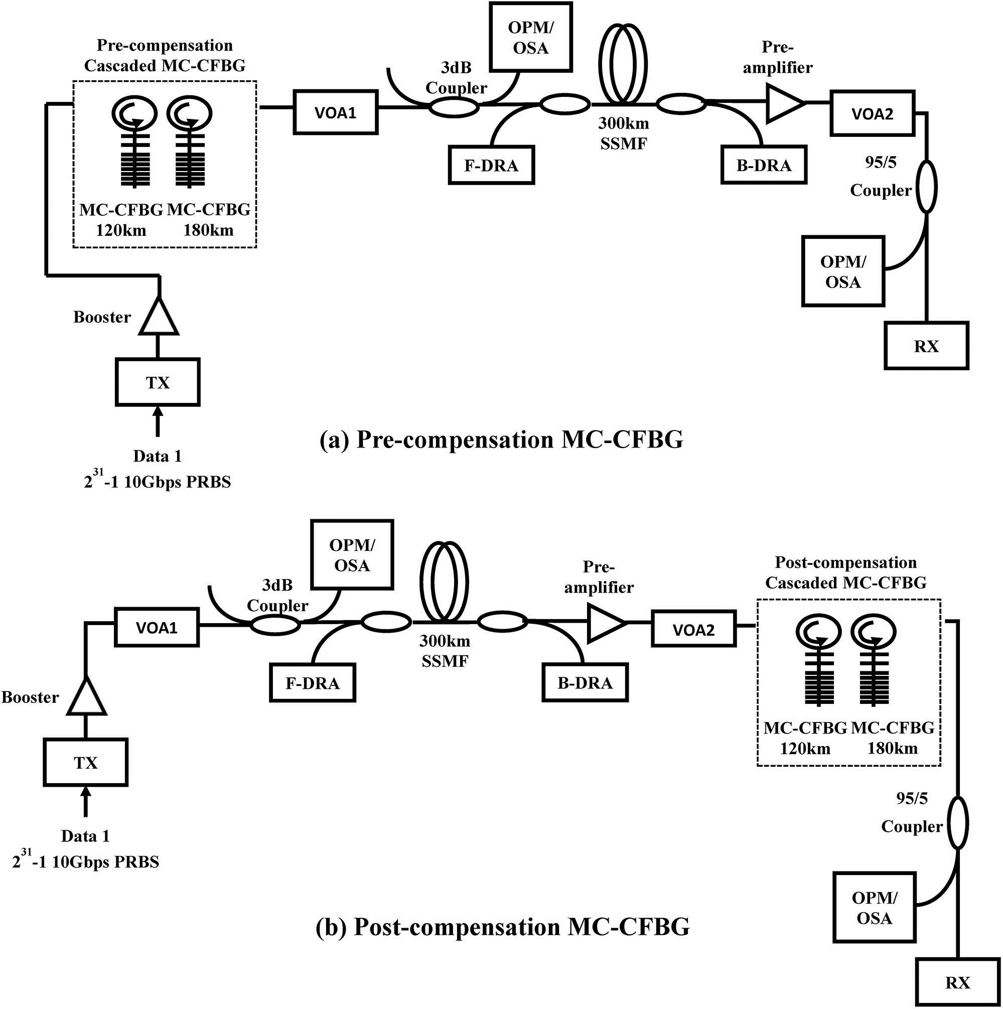
Figure 1(a) shows the experimental setup of pre-compensation cascaded MC-CFBG (close to TX), and Figure 1(b) is the post-compensation cascaded MC-CFBG configuration (close to RX) over the 300 km repeaterless transmission system. In the configurations, the TX uses non-return-to-zero differential phase shift keying (NRZ-DPSK) modulation format, as it has a higher RX sensitivity and a lower impact on nonlinearities as well as signal fluctuations at the RX[19,20]. In the experimental setup, the TX is operating at 1548.51 nm. The TX laser is modulated with 10 Gbps (data) at eudorandom bit sequence (PRBS) through the Mach–Zehnder modulator (MZM).

Figure 1.Experimental setup: (a) pre-compensation and (b) post-compensation cascaded MC-CFBG of single-channel 10 Gbps repeaterless transmission system over 300 km SSMF.
The modulated signal is amplified by a booster with an average power at 18.6 dBm. For the pre-compensation configuration setup [Fig. 1(a)], the amplified signal passes through the pre-compensation cascaded MC-CFBG and variable optical attenuator 1 (VOA1) to the transmission link. VOA1 is used to control the transmission power to the transmission link, and the signal is monitored using a 3 dB coupler. The signal is then transmitted to a 300 km FOC link through forward-distributed Raman amplifier (F-DRA). The challenge of repeaterless system is the requirement to have sufficient optical signal to noise ratio (OSNR) as high attenuation occurs due to long fiber spans. Therefore, DRA was used to maintain system margin with an adequate OSNR for the system to operate in an optimum performance. The output power of F-DRA is optimized from two pump wavelengths at 1445 and 1455 nm. The total power of F-DRA is 0.762 W, and the on–off gain is 15 dB. The design uses a typical terrestrial deployment FOC with an average fiber loss of 0.18 dB/km. The measured dispersion is 5051 ps/nm at 1550 nm with a slope of . The total insertion loss (IL) of the 300 km FOC is 60 dB.
For configuration of pre-compensation and post-compensation MC-CFBG, two units of MC-CFBG are cascaded with the combination of MC-CFBG, as depicted in Table 1. The dispersion value for each MC-CFBG displayed is the value to compensate km of the FOC in a transmission.
| | Dispersion Value |
|---|
| Pre-compensation | −2006.0 ps/nm at 120 km and −3008.0 ps/nm at 180 km |
| −2338.3 ps/nm at 140 km and −2674.0 ps/nm at 160 km |
| Post-compensation | −2006.0 ps/nm at 120 km and −3008.0 ps/nm at 180 km |
| −2338.3 ps/nm at 140 km and −2674.0 ps/nm at 160 km |
Table 1. MC-CFBG Composition in the Experimental Setup
The received signal after 300 km is countered by backward-DRA (B-DRA) at the receiving side using three pump wavelengths at 1430, 1440, and 1450 nm. The total pump power is 0.858 W with the on–off gain of 32 dB. The received signal is further amplified by a pre-amplifier with 16 dB gain and 5.5 dB noise figure. In order to measure the RX sensitivity of the transmission system, VOA2 is used to change the received power and is monitored through the 5% port of a 95/5 coupler. The 95% transmission signal is directly detected at the RX, and the signal quality is then measured using Alnair Photonics SeBERT-100 BER tester (BERT).
For the post-compensation setup illustrated in Fig. 1(b), the TX signal passes through the booster, VOA1, 3 dB coupler, and F-DRA. The configuration setting for both the booster and F-DRA is similar to the previous setup with only a change in the transmitting power to the transmission link, which is dependent on the VOA1 setting. The transmission signal after 300 km FOC is received at the B-DRA, pre-amplifier; the signal is then compensated through post-compensated cascaded MC-CFBG before measuring its performance at the receiving end.
The effect of pre-compensation and post-compensation cascaded MC-CFBG is further investigated by implementing the wavelength division multiplexing (WDM) channel over the 10 Gbps repeaterless transmission system. Figure 2 shows the experimental setup of a repeaterless transmission system with different composition of MC-CFBG, as depicted within the dotted line. In the configuration, the transmission system is tested with two conditions: single channel (1548.51 nm) and four channels (1546.9, 1547.7, 1548.51, and 1549.2 nm, 100 GHz spacing). The signal wavelength of 1548.51 nm is connected to the first NRZ-DPSK modulator, which is driven by a 10 Gbps with PRBS length of (Data 1). The other three channels are multiplexed through an array waveguide (AWG1) and connected to another NRZ-DPSK modulator (the second TX) that is driven by a 10 Gbps with PRBS length of (Data 2). The TX that operates at the 1548.51 nm laser diode (LD3) is the intended TX and the others are treated as interferers. All modulated signals are then combined using a 3 dB coupler, and the WDM signals are viewed and measured with an optical spectrum analyzer (OSA).
Figure 2.Experimental setup for WDM channel of 10 Gbps repeaterless transmission system.
The configuration for F-DRA and B-DRA is optimized to a higher current pump in order to obtain adequate output power for the WDM channel. The total pump power of F-DRA and B-DRA is 0.762 W and 1.1 W, respectively. The BER performance of the intended channel is measured by filtering the WDM channel via AWG2. VOA2 is varied in order to obtain a different level of received power at RX3.
The performance of BER as a function of launch power and received power for all configurations is measured and analyzed. The optical spectrum of the received signal for pre-compensation cascaded MC-CFBG and post-compensation cascaded MC-CFBG is shown in Fig. 3. The spectrum width is measured at a 3 dB threshold to quantify the width of all received signals. The original transmitted optical spectrum width is 0.069 nm. However, with a different placement of MC-CFBG as well as composition value of MC-CFBG, the spectrum width broadened as compared to the transmitted signal. It can be seen in the figure below as the pre-compensation cascaded MC-CFBG’s spectrum width increased to 0.073 nm. The traveling signal propagates at different speeds due to self-phase modulation (SPM) together with group velocity delay (GVD), which leads to spectrum broadening at the receiving end. In addition, the spectrum of pre-compensation cascaded MC-CFBG suffered from high noise as the signal that propagated along the distance is not filtered at the receiving end. Further investigation of the effect is evaluated with BER performance for all configurations.
Figure 3.Optical spectra (resolution ) of transmitted and received signals of single-channel transmission.
The experimental results displayed in Fig. 4 show the BER performance as a function of launch power and received power for pre-compensation cascaded MC-CFBG. The BER performance was optimized by varying the launch power to the transmission fiber, and the best BER in a function of launch power was selected (circle), as shown in Fig. 4(a). During the measurement, the received power is fixed. For the BER measurement with variation of received power, the launch power is set to 1 dBm. In Fig. 4(b), the performance of both configurations is also compared with back-to-back measurement. By taking the BER at as a reference, the penalty is about 40 dB compared to the back-to-back setup. This large penalty is attributed to the noise produced by amplifiers in the system. Therefore, the optical signal to noise ratio level of the signal had degraded. The signal also experienced a nonlinearity effect, such as SPM. Due to a stronger SPM that had accumulated with distance, the signal could not be reshaped to the original transmitted signal using linear compensation; thus, the received spectra broaden at the receiving end. The signal pulse broadens temporally; this leads to the signal pulse overlapping between neighboring bits and, therefore, an increase in the BER.
Figure 4.(a) BER versus launch power and (b) BER versus received power of pre-compensation cascaded MC-CFBG over 10 Gbps single-channel repeaterless system.
On the other hand, the performance for post-compensation cascaded MC-CFBG configurations in Fig. 5 showed an improvement. The error free can be achieved when the launch power was 7 to 10 dBm. The SPM effect can be seen after 10 dBm power was launched to the transmission fiber. The launch power for the post-compensation configuration is higher compared to that for the pre-compensation configuration, which is due to high tolerance to the nonlinearity effect of the post-compensation configuration. The power penalty of 5 dB, as depicted in Fig. 5(b), is due to the noise produced by amplifiers in the system. The configuration showed that the RX sensitivities satisfied the BER performances, as the results achieved are below the forward error correction (FEC) threshold requirements.
Figure 5.(a) BER versus launch power and (b) BER versus received power of post-compensation cascaded MC-CFBG.
The performance comparison between pre-compensation cascaded MC-CFBG and post-compensation cascaded MC-CFBG is conducted. The configuration of pre-compensation cascaded MC-CFBG showed severe distortion as compared to that of post-compensation cascaded MC-CFBG with 9 dB (optimum value of BER of both configurations) and 35 dB penalty (reference level at BER ). The huge gap is explained as being due to such impairments, the SPM effect, and high noise.
The performances of pre-compensation and post-compensation over the WDM system with a comparison of a single channel and the WDM channel are plotted in Figs. 6 and 7. As mentioned above, the effect of SPM contributed to the signal distortion over the single-channel transmission, particularly in the pre-compensation configuration. With multiple signals propagating through a transmission fiber, the effect of each channel will be twice as strong as compared to the individual, as there will be increased collective phenomena of the SPM effect. Therefore, cross phase modulation (XPM) is sturdier compared to that in SPM. The XPM will result in phase modification of the signal itself with the addition of other incoming signals, which co-exist along with the signals. The different signals carry power density within the transmission fiber, therefore modifying the phase due to the change of the refractive index. Therefore, the results are explained through Figs. 6 and 7, where there is an increase of error in a bit transmission.
Figure 6.BER versus (a) launch power and (b) received power of pre-compensation for single channel and WDM channel.
Figure 7.(a) BER versus launch power and (b) BER versus received power of post-compensation for single channel and WDM channel.
For the performance of pre-compensation cascaded MC-CFBG, by evaluating BER as a function of launch power and received power, the differences are the 5 and 12 dB penalty, respectively. It also can be observed at post-compensation cascaded MC-CFBG by taking BER at as a reference, where the single channel benefits from the WDM channel at 9 and 5.5 dB with respect to the BER against launch power and received power. However, the WDM channel performance for post-compensation cascaded MC-CFBG managed to achieve a BER at , which is within the FEC threshold.
In conclusion, the post-compensation configuration displayed an optimal performance for the single channel and WDM channel of a repeaterless system. The implementation of post-compensation cascaded MC-CFBG for future designs and planning of transmission systems particularly for repeaterless transmission systems is thoroughly recommended.
References
[1] V. Watanabe, V. Anderson. FUJITSU Sci. Tech. J., 45, 34(1999).
[2] Y. Inada, Y. Kanno, I. Matsuoka, T. Inoue, T. Nakano, T. Ogata. NEC Corporation, SubOptic, 1, 1(2010).
[3] Y. Inada, T. Ito, K. Fukuchi, T. Koga, T. Ogata. SubOptic(2007).
[4] G. Charlet. Proc. SPIE, 6353, 635316(2006).
[5] T. J. Xia, D. L. Peterson, G. A. Wellbrock, D. Il Chang, P. Perrier, H. Fevrier, S. Ten, C. Tower, G. Mills. Optical Fiber Communication Conference and Exhibition, 5(2014).
[6] D. A. Mongardien. 36th European Conference and Exhibition on Optical Communication (ECOC), 4.05(2010).
[7] J. D. Downie, J. Hurley, J. Cartledge, S. Ten, S. Bickham, S. Mishra, X. Zhu, A. Kobyakov. 36th European Conference and Exhibition on Optical Communication (ECOC), We.7.C.5(2010).
[8] B. Bakhshi, S. Papernyi. 31st European Conference on Optical Communication (ECOC), 73(2005).
[9] S. Bhandare, A. Joshi, D. Becker. J. Lightwave Technol., 28, 47(2010).
[10] J. D. Downie, J. Hurley. Opt. Express, 15, 9527(2007).
[11] C. Wree, S. Bhandare. Photon. Technol., 20, 407(2008).
[12] T. Ilavarasan, M. Meenakshi. J. Opt., 44, 255(2015).
[13] E. Iannone. Telecommunication Networks(2012).
[14] N. M. Sharif, A. H. Sulaiman, M. A. Mahdi. 1st International Conference on Telematics and Future Generation Networks (TAFGEN), 107(2015).
[15] K. Khairi, Z. Lambak. RF Microw., 254(2011).
[16] M. Hayee, A. Willner. IEEE Photon. Technol. Lett., 9, 1271(1997).
[17] C. Peucheret, N. Hanik, R. Freund, L. Molle, P. Jeppesen. IEEE Photon. Technol. Lett., 12, 992(2000).
[18] I. Navruz, A. Altuncu. New Trends in Computer Networks - 20th International Symposium on Computer and Information Sciences, 114(2005).
[19] J. Lasobras, A. Villafranca. Optical Fiber Communication Conference and National Fiber Optic Engineers Conference, 2(2009).
[20] P. J. Winzer, R.-J. Essiambre. Proc. IEEE, 94, 952(2006).
[21] M. Haris, J. Yu, G. Chang. Conference on Lasers Electron, 2(2006).