We propose a scheme to obtain a low-loss propagation of Airy surface plasmon polaritons (SPPs) along the interface between a dielectric and a negative-index metamaterial (NIMM). We show that by using the transverse-magnetic mode and the related destructive interference effect between electric and magnetic absorption responses, the propagation loss of the Airy SPPs can be largely suppressed when the optical frequency is close to the lossless point of the NIMM. As a result, the Airy SPPs obtained in our scheme can propagate more than a 6 times longer distance than that in conventional dielectric–metal interfaces.
Dielectric–metal interfaces are known to support surface plasmon polaritons (SPPs), i.e., surface electromagnetic waves propagating along the planar interface between a metal and a dielectric material. These particular electromagnetic modes are sustained by collective electronic oscillations in the metal near the interface, and are essentially two-dimensional waves with field components decaying exponentially with distance from the interface. The fact that SPPs can overcome the diffraction limit and localize light within a subwavelength volume makes them ideal tools for enhancing light–matter interactions[1].
In recent years, much attention has been paid to the study of Airy light beams[2]. Unlike most types of light waves, Airy beams have the ability to resist diffraction, and can freely bend without requiring waveguiding structures or external potentials[3]. Up until now, Airy beams have been found in various fields of physics including optics[2,4–6], spin waves[7], plasma[8], and electron beams[9]. They also have a wide range of applications including trapping, guiding, manipulation of objects[10,11] and slow lights in cold atomic gases[12,13], signal processing[14], molecular diagnostics, and biosensing applications.
Recently, Airy beams have been introduced theoretically by Salandrino and Christodoulides for controlling SPPs along dielectric–metal interfaces[15]. This work presented an opportunity for realizing nondiffracting SPPs, and stimulated flourishing experimental activities on Airy SPPs along dielectric–metal interfaces[16] (also see references therein). However, Airy SPPs found up until now have had a very short propagation distance due to the large Ohmic loss inherent in metals, which severely limits practical applications of Airy SPPs.
Sign up for Chinese Optics Letters TOC. Get the latest issue of Chinese Optics Letters delivered right to you!Sign up now
In this work, we suggest a scheme to generate low-loss Airy SPPs, which propagate along the interface between a dielectric and a negative-index metamaterial (NIMM)[17,18]. By using the transverse-magnetic mode and the related destructive interference effect between the electric and magnetic absorption responses, we show that the propagation loss of the Airy SPPs can be suppressed significantly. As a result, the Airy SPPs obtained in our work can propagate more than a 6 times longer distance than that in conventional dielectric–metal interfaces, after taking the inherent diffraction effect into account.
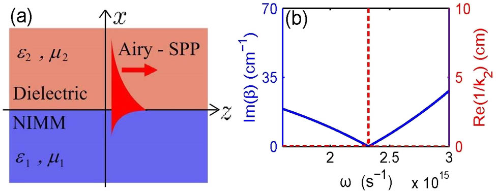
The system we consider consists of two superposed planar materials, i.e., a dielectric and a NIMM (which could be replaced by a metal for comparison), with a planar dielectric–NIMM interface, as shown in Fig. 1(a). The NIMM in the lower half-plane () has permittivity and permeability (which are frequency-dependent), and the dielectric in the upper half-plane () has permittivity and permeability (which are taken as frequency-independent constants).
Figure 1.(a) Dielectric-NIMM interface. NIMM (in the lower half-plane, ) has frequency-dependent permittivity and permeability . Dielectric (in the upper half-plane, ) has frequency-independent permittivity and permeability . SPP propagates along -direction; (b) (blue solid line) and (red dashed line) as functions of oscillating frequency .
We choose the Drude model to describe the electric permittivity and magnetic permeability of the NIMM[19], i.e., and , where and are the electric and magnetic plasmon frequencies, and are the corresponding decay rates, and and are background constants. For comparison, the parameters for conventional metals are given by [i.e., ] and .
The dielectric–NIMM interface supports both transverse electric and transverse magnetic modes. Here we focus only on the transverse magnetic modes. We assume that the SPP propagates in the positive direction and the direction is perpendicular to the interface. Then the form of electromagnetic field is taken as (“+” corresponds to for the NIMM, and “−” corresponds to for the dielectric). Here () are slowly varying envelope functions and (with being the propagation constant, , and ) satisfies the boundary condition . It is easy to obtain the linear dispersion relation of the system The aforementioned model can be realized by using a silver-based NIMM, with the structure of sandwich. The parameters are chosen as[19]: , , , and . The background constants are fixed as . We shall also use Ag to replace the NIMM for comparison. The parameters for the dielectric are chosen as and . The SPP can be generated via the optical grating coupling or prism coupling technique along the surface of the NIMM under the phase-matching condition.
In Fig. 1(b), we show the imaginary part of propagation constant, Im(), based on Eq. (1), and the real part of transverse confinement, . We see that the Ohmic loss of the NIMM can be completely suppressed at a particular frequency , where . The physical reason for such suppression is due to the destructive interference between the electric- and magnetic-field absorptions of the NIMM because and are both negative.
However, the complete suppression of the Ohmic loss is unfortunately accompanied by a deconfinement of the SPP in the dielectric, i.e., when . In order to obtain a significant suppression of the Ohmic loss and a required SPP confinement simultaneously, one must choose the optical frequency to have a small deviation from the lossless point . Here we take . As a result, a small absorption exists for the confined SPP.
In Fig. 2, we show for a dielectric–NIMM interface and a dielectric–metal interface for comparison. We see that, distinct from the dielectric–NIMM interface, for the dielectric–metal interface has no zero point, i.e., there is no destructive interference. With the given parameters, we obtain that , (blue dot), and (red dot) at . Consequently, the propagation loss of the dielectric–metal interface is much larger than that of the dielectric–NIMM interface.
Figure 2. of the SPP as a function of at the dielectric–NIMM interface (blue solid line) and the dielectric–metal interface (red dashed line). (blue dot) and (red dot) at .
We now consider the propagation of an Airy SPP along the dielectric–NIMM interface. We stress that full vector Maxwell’s equations and related boundary conditions must be considered because the optical field is localized at the interface within a subwavelength volume[20]. () satisfy the Helmholtz equation ; in other words
The first step to obtain Airy SPP solutions is to derive the envelope equation for SPP propagation, which can be obtained by employing a method of multiple scales[19]. To this end, we consider a group of multi-scale variables , , and , where is a dimensionless small parameter. In addition, we take the following asymptotic expansions: , and , with all quantities on the right-hand side in the square bracket being considered as functions of multi-scale variables , , and .
At the -order, we obtain the equation , which admits the solution , with the envelope dependent on the slow variables due to the modulation by the dielectric. In addition, . From the boundary condition , one can obtain . The solution of can be obtained at the -order, which is skipped here due to space limitations.
At the -order, we obtain the equation , with . A solvability condition at this order requires that , which can be written into a dimensionless form, reading as . Here , , and , with () the typical width (amplitude) of the light field. Note that in the aforementioned derivation the imaginary part of is neglected because it is much smaller than the corresponding real part (the small imaginary part will be considered in the numerical simulation next). The equation for admits a finite-power Airy function solution[2]: . Here, is a small positive parameter introduced to avoid the divergence of the light power of the beam. The initial condition is , which can be generated by using a spatial light modulator.
With the aforementioned solution, when returning to the original variables we obtain the Airy SPP of the system We see that the Airy SPP generated in the dielectric–NIMM interface propagates along a parabolic trajectory and preserves their wave shape during propagation.
Shown in Figs. 3(a) and 3(b) are intensity profiles of the Airy SPPs at the dielectric–NIMM interface and dielectric–metal interface, respectively. The parameters are taken as and with other parameters being the same with those used in Fig. 2. We see that at the dielectric–NIMM interface the Airy SPP can propagate to a long distance without obvious attenuation. This is because the absorption of the Airy SPP due to the Ohmic loss of the NIMM is largely suppressed. However, at the dielectric–metal interface the Airy SPP propagates only for a short distance and attenuates due to the significant Ohmic loss. To see this more clearly, we define the absorption length of the Airy SPP as . From the aforementioned results we obtain Thus, the absorption length of the dielectric-NIMM interface is more than 6 times larger than that of the dielectric–metal interface, which means that the Airy SPP obtained in the dielectric–NIMM interface may propagate more than a 6 times longer distance than that in the dielectric–metal interface.
Figure 3.(a) Intensity profile of the Airy-type SPPs at the dielectric–NIMM interface; (b) intensity profile of the Airy-type SPPs at the dielectric–metal interface; (c) maximum intensity as a function of in free-space (blue solid line), the dielectric–NIMM interface (red dashed line), and the dielectric–metal interface (green dash–dot line). Parameters are taken as and . Other parameters are the same as those used in Fig. 2.
Figure 3(c) shows the maximum intensity, , as a function of the propagating distance in free-space, the dielectric–NIMM interface, and the dielectric–metal interface. We see that the curve of the dielectric–NIMM interface is much closer to the curve of the free-space than that of the dielectric–metal interface, indicating that there is only slight absorption in the dielectric–NIMM interface. However, the dielectric–metal interface exhibits a significant absorption.
In conclusion, we propose a scheme to obtain a low-loss propagation of Airy SPPs along the dielectric–NIMM interface. By using the transverse-magnetic mode and the related destructive interference effect between electric and magnetic absorption responses, we show that the propagation loss of the Airy SPPs can be largely suppressed when the optical frequency is close to the lossless point of the NIMM. As a result, the Airy SPPs obtained in our scheme can propagate more than a 6 times longer distance than that in conventional dielectric–metal interfaces. The low-loss and nondiffraction characteristics of the Airy SPPs at the dielectric–NIMM interface may have promising applications in light and quantum information processing at the nanoscale.
References
[1] S. A. Maier. Polaritonics: Fundamentals and Applications(2007).