
Huicun Yu, Bangying Tang, Jiahao Li, Yuexiang Cao, Han Zhou, Sichen Li, Haoxi Xiong, Bo Liu, Lei Shi, "Satellite-to-aircraft quantum key distribution performance estimation with boundary layer effects," Chin. Opt. Lett. 21, 042702 (2023)
- Chinese Optics Letters
- Vol. 21, Issue 4, 042702 (2023)
Abstract
1. Introduction
Based on quantum mechanics, quantum key distribution (QKD) can realize security key sharing between remote communication parties, which plays an important role in our modern information society[1–5]. In order to build the integrated quantum communication network, substantial progress has been achieved in both theoretical and experimental aspects, especially those that are fiber-based[6–9] and satellite-based[10–16] QKD. In 2021, the world’s first large-scale quantum communication network was constructed that integrated more than 700 terrestrial optical fiber QKD links and two high-speed QKD links in satellite-terrestrial free space, which enabled any user in the network to communicate in a distance of 4600 km[16]. It shows that the quantum satellites can effectively provide QKD service even at the intercontinental scale and construct ultralong-distance global quantum networks. However, there are still some places where terrestrial fiber and ground stations cannot be constructed, like harsh mountainous areas, and air space above the sea. So airborne quantum nodes are expected to replace ground stations and provide flexible and relay links for large-scale integrated communication networks[17]. Compared with satellite-to-station QKD, satellite-to-aircraft QKD features low atmospheric loss and long transmission distance, owing to the photon loss and turbulence predominantly occurring in the lower
Since the first aircraft-based QKD experiment was verified successfully in 2013[19], in the past decade, numerous studies have been focusing on the challenges of airborne QKD links[19–25]. Compared with ground stations, airborne QKDs feature high-speed maneuverability and suffer complicated atmosphere conditions that include atmospheric turbulence[26–30], background noise[31–33], and attitude disturbance[14]. Furthermore, a very thin layer of air will stick over the surface of the aircraft with high velocity, resulting in the boundary layer (BL)[34,35]. It has been proved that the BL effect will seriously affect the airborne QKD performance when the aircraft speed is higher than 0.3 Ma[36]. However, previous research of airborne QKD with BL effects is mainly under the air-to-ground scenario, while the satellite-to-aircraft scenario, which is one of the essential components in constructing a globe-wide quantum-secure communication network, has rarely been reported.
In this article, we propose a performance evaluation scheme of satellite-to-aircraft QKD with BL effects. We first propose a satellite-to-aircraft QKD scenario with decoy BB84 protocol. Then, the wavefront aberration of quantum signal states is evaluated by estimating the reflection index distribution of the surrounded BL and performing the ray tracing method by the Adams linear multistep method, which starts with the satellite ephemeris and aircraft trajectory. Afterward, the photon transmission efficiency caused by wavefront aberration is evaluated by the Strehl ratio. Finally, the overall photon quantum bit error rate (QBER) and final secure key rate can be estimated. The analyzed photon transmission loss in different incident angles shows that the effects of the BL are more serious when the aircraft moves towards the satellite. With common experimental settings, the BL would introduce a 31 dB loss to the transmitted photons, decrease
2. Preliminaries
2.1. Reference system conversions
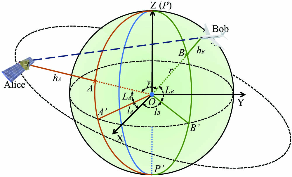
The coordinates of satellite and aircraft in the WGS-84 coordinate system can be obtained from the satellite ephemeris and aircraft trajectory, as shown in Fig. 1. The points P and
![]()
Figure 1.Schematic diagram of satellite and aircraft in the WGS-84 coordinate system.
In the ray-tracing methods, the satellite azimuth angle, the satellite elevation angle, and the distance between the satellite and aircraft are taken as the input parameters. Therefore, it is necessary to transform the WGS-84 coordinate system into the spherical coordinate system based on the aircraft, as shown in Fig. 2. The spherical coordinate system is established with the origin at the geometric center of the airborne receiver telescope. The
![]()
Figure 2.Schematic diagram of downlink satellite-to-aircraft QKD in the spherical coordinate system based on the aircraft. The satellite (Alice) flies in a certain orbit above the receiving aircraft (Bob).
2.2. Principle of ray-tracing methods
The aero-optical effects are fundamentally caused by the gradient refractive index
The trajectory of a ray in inhomogeneous media is determined by solving the ray equation[38],
The ray path can be calculated by numerical solution[39,40].
2.3. Aero-optical effects
In the airborne QKD procedure, the BL effect is also called the aero-optical effect in classical optics. Aero-optical effects will be introduced to the photons, which are propagated through the density-varying flow field of the BL. Typical aero-optical effects mainly include wavefront aberration, jitter, intensity attenuation, and so on. Relevant parameters of aero-optical effects are the optical path length (OPL), the optical path difference (OPD), and the Strehl ratio (SR)[41].
The refractive index field of the airborne BL can be calculated by dividing the density field
The OPL of the photons is calculated by integrating the refractive index
OPD shows the configuration of the wavefront and is defined as
The overline denotes the spatial average over the optical aperture. The phase difference of the photons can be defined by
There is a distance between the BL and receiver telescope, as shown in Fig. 3, which depends on whether the aircraft is a transmitter or receiver in the airborne QKD scenario. When the transmission distance is similar to the communication distance, all aero-optical effects introduced by the BL need to be considered. However, when the distance is far less than communication distance, even if the effect of the BL is introduced into the divergence angle and the deflection angle, the deflection and divergent effect could be ignored, but the wavefront aberration should be taken into consideration. As the distance is far less than communication distance in the satellite-to-aircraft downlink QKD scenario, only the wavefront aberration would have been taken into consideration.
![]()
Figure 3.Schematic diagram of the distance between the BL and receiver telescope.
3. Satellite-to-Aircraft QKD with BL Effects
Previous research on airborne QKD with BL effects is mainly under the air-to-ground scenario, with the aircraft as the transmitter and the ground station as the receiver. In this paper, the satellite is the transmitter and the aircraft is the receiver. The primary difference is that the distance between the BL and the receiving telescope is long in the air-to-ground scenario, whereas the distance is tight in the satellite-to-aircraft scenario. As mentioned in Section 2.3, due to the different distance, the performance evaluation schemes are different in the two scenarios. The performance evaluation procedure for satellite-to-aircraft QKD scheme is shown in Fig. 4.
![]()
Figure 4.Diagram of the satellite-to-aircraft QKD performance evaluation.
3.1. Satellite-to-aircraft downlink QKD scenario
The satellite-to-aircraft downlink QKD scenario is shown in Fig. 2, the quantum photon source is located at the satellite (Alice), and the QKD receiving module with a spatial single-mode receiver is fixed in the upper fuselage of the aircraft (Bob). The receiver telescope position is temporarily set in a reasonable range. Assume that Alice is flying with a constant velocity, direction, and altitude. Given the aircraft specification, speed
According to Section 2.1, the time-varying data of azimuth angle
3.2. Satellite-to-aircraft QKD performance evaluation
The performance evaluation procedure for satellite-to-aircraft QKD scheme mainly contains three steps: photon aberrations evaluation, transmission efficiency calculation, and key rate estimation, as shown in Fig. 4.
3.2.1. Photon aberration
According to the downlink satellite-to-aircraft QKD scenario, the distance between the BL and the receiving telescope is tiny. The deflection and divergent effect from aero-optics can be ignored, and the effective beam waist of the downlink photon at the receiving telescope is constant, no matter whether the BL exists or not.
When the Gaussian mode beam is propagating through the BL to the aircraft, the effective beam waist
According to Section 2.1, we establish the spherical coordinate system with the origin at the geometric center of the airborne receiver telescope, as shown in Fig. 5. We take sufficient incident points uniformly in the light spot range with the radius of the effective beam waist
![]()
Figure 5.Schematic diagram of photon aberrations evaluation. The photons propagate through the BL to the receiver telescope, and the wavefront aberration can be calculated by the ray-tracing method.
The initial values
3.2.2. Transmission efficiency
When the beam propagates through the BL and illuminates the receiving telescope, the transmission efficiency
In the satellite-to-aircraft QKD system, the photon transmission efficiency
3.2.3. Secure key rate estimation
The decoy state is a common method in implemented experiments that combine with the QKD protocols like BB84 and measurement device independent (MDI) QKD, which can efficiently defend against the photon number splitting attacks and can perform the weak coherent photon source to replace the single-photon source in the implementations. The decoy state QKD protocol has been widely performed in fiber-based, satellite-based, and airborne-based QKD systems. Thus, in the satellite-to-aircraft QKD scheme, we perform weak-vacuum decoy BB84[48] protocol with signal photon intensity
Given the photon transmission efficiency
Thus, the QBER
The gain of single-photon states
The error rate of single-photon states
The error gain of decoy states
Afterward, the QBER
4. Performance Analysis
The specific parameters of the aircraft, quantum photon source payload, and optical receiving module are shown in Table 1. Some parameters refer to the Micius quantum experiment science satellite in the literature[10].
| Payload | Parm. | Description | Value |
|---|---|---|---|
| Aircraft | v | Flight speed | 0.7 Ma |
| hB | Altitude of aircraft | 10 km | |
| ρh | Air density | 0.413 kg/m3 | |
| τ | Extinction optical thickness[ | 0.02 | |
| Photon source | DT | Diameter of the transmitter telescope | 0.3 m |
| δT | Transmitter pointing precision[ | 10 µrad | |
| λ | Transmitter wavelength | 1550 nm | |
| ω0 | Waist radius | 0.0949 m | |
| r0 | Fried parameter in zenith[ | 0.4 m | |
| μ | Intensity of signal states | 0.8 | |
| ν | Intensity of decoy states | 0.1 | |
| N | System repetition rate | 100 MHz | |
| Ps | Probability of signal states | 50% | |
| Pd | Probability of decoy states | 30% | |
| Pv | Probability of vacuum states | 25% | |
| Receiving module | DR | Diameter of the receiver telescope | 0.5 m |
| ed | System detection error rate | 1% | |
| pd | Dark count rate | 2 × 10⁻⁶ | |
| ηd | Detector efficiency | 50% | |
| ηs | Receiving optical module efficiency | 60% |
Table 1. Parameters of Airborne QKD
Here, the typical wing-body configuration DLR-F6 is chosen for the performance analysis of our specified satellite-to-aircraft QKD system. Given the detailed aircraft description from Table 1, the BL will be generated around the DLR-F6[49] and its density field distribution can be simulated by the computational fluid dynamics software (Ansys Fluent), as shown in Fig. 6. Assuming that the receiver telescope that conforms with the aircraft is fixed in the symmetry axis of the upper fuselage surface, the
![]()
Figure 6.Evaluated density field distribution of the DLR-F6 BL. The dimensions of the BL are
In the coordinate system shown in Fig. 6, assume that the satellite orbits the earth at an altitude of 500 km that is directly over the aircraft at various azimuths. Setting azimuth angle α = 0°, 90°, 180°, 270° and elevation angle
![]()
Figure 7.Total loss over the different incident angles. Here they are α = 0°, 90°, 180°, 270°.
Assume that the aircraft is flying at a constant speed
![]()
Figure 8.Schematic diagram of satellite-to-aircraft QKD from 12:00 on May 29, 2022, to 12:00 on June 5, 2022. The yellow arrow indicates the direction of flight of the aircraft.
Then, during a week, the performance of the whole satellite-to-aircraft QKD session is evaluated. When the aircraft is heading south, the result is shown in Fig. 9. Significantly, the abscissa represents the link time of all established links in a week, and the total link time is 6800 s. The additional channel loss to the transmitted photons is around 30 dB during the total link time, as shown in Fig. 9(a). The time when the secure key rate is more than zero is denoted as the quantum communication time. Therefore, the total quantum communication time is 3625 s, as shown in Fig. 9(c), and the estimated total final key size is around
![]()
Figure 9.(a) Total loss in the satellite-to-aircraft QKD scenario; (b) estimated QBER over the communication time; (c) secure key rate over the communication time. The value of X0 is 66 mm and the aircraft flights toward the south. The intensity of signal states is 0.8, and the intensity of decoy states is 0.1.
![]()
Figure 10.(a) Total loss in the satellite-to-aircraft QKD scenario; (b) estimated QBER over the communication time; (c) secure key rate over the communication time. The value of X0 is 66 mm and the aircraft flights toward the east. The intensity of signal states is 0.8, and the intensity of decoy states is 0.1.
5. Conclusion
Airborne QKD will be a flexible bond between the terrestrial fiber QKD network and quantum satellites, which can establish a mobile, on-demand, and real-time coverage quantum network. However, the randomly distributed BL always surrounds the surface of the aircraft, which would introduce random wavefront aberration, jitter, and extra intensity attenuation to the transmitted photons between the aircraft and the ground station. Previous research of airborne QKD with BL effects is mainly under the air-to-ground scenario, while the satellite-to-aircraft scenario is rarely reported. In this article, we proposed a detailed performance evaluation scheme of satellite-to-aircraft QKD with BL effects. The analyzed photon transmission loss shows that the effects of the BL are more serious when the aircraft moves towards the satellite. In our proposed satellite-to-aircraft QKD scenario, the BL would introduce
References
[1] I. M. Arbekov, S. N. Molotkov. Secret keys agreement in communication networks with quantum key distribution and trusted nodes. Laser Phys. Lett., 17, 055202(2020).
[2] C. Erven, B. Heim, E. Meyer-Scott, J. P. Bourgoin, R. Laflamme, G. Weihs, T. Jennewein. Studying free-space transmission statistics and improving free-space quantum key distribution in the turbulent atmosphere. New J. Phys., 14, 123018(2012).
[3] E. Kaur, M. M. Wilde, A. Winter. Fundamental limits on key rates in device-independent quantum key distribution. New J. Phys., 22, 023039(2020).
[4] N. Lütkenhaus, A. J. Shields. Focus on quantum cryptography: theory and practice. New J. Phys., 11, 045005(2009).
[5] D. Stucki, M. Legré, F. Buntschu, B. Clausen, N. Felber, N. Gisin, L. Henzen, P. Junod, G. Litzistorf, P. Monbaron, L. Monat, J.-B. Page, D. Perroud, G. Ribordy, A. Rochas, S. Robyr, J. Tavares, R. Thew, P. Trinkler, S. Ventura, R. Voirol, N. Walenta, H. Zbinden. Long-term performance of the SwissQuantum quantum key distribution network in a field environment. New J. Phys., 13, 123001(2011).
[6] W. Chen, Z. Han, T. Zhang, H. Wen, Z. Yin, F. Xu, Q. Wu, Y. Liu, Y. Zhang, X. Mo, Y. Gui, G. Wei, G. Guo. Field experiment on a “star type” metropolitan quantum key distribution network. IEEE Photon. Technol. Lett., 21, 575(2009).
[7] S. Wang, W. Chen, Z.-Q. Yin, D.-Y. He, C. Hui, P.-L. Hao, G.-J. Fan-Yuan, C. Wang, L.-J. Zhang, J. Kuang, S.-F. Liu, Z. Zhou, Y.-G. Wang, G.-C. Guo, Z.-F. Han. Practical gigahertz quantum key distribution robust against channel disturbance. Opt. Lett., 43, 2030(2018).
[8] X.-B. Wang, Z.-W. Yu, X.-L. Hu. Twin-field quantum key distribution with large misalignment error. Phys. Rev. A, 98, 062323(2018).
[9] W. Kozlowski, S. Wehner. Towards large-scale quantum networks. Proceedings of the Sixth Annual ACM International Conference on Nanoscale Computing and Communication, 3(2019).
[10] S.-K. Liao, W.-Q. Cai, W.-Y. Liu, L. Zhang, Y. Li, J.-G. Ren, J. Yin, Q. Shen, Y. Cao, Z.-P. Li, F.-Z. Li, X.-W. Chen, L.-H. Sun, J.-J. Jia, J.-C. Wu, X.-J. Jiang, J.-F. Wang, Y.-M. Huang, Q. Wang, Y.-L. Zhou, L. Deng, T. Xi, L. Ma, T. Hu, Q. Zhang, Y.-A. Chen, N.-L. Liu, X.-B. Wang, Z.-C. Zhu, C.-Y. Lu, R. Shu, C.-Z. Peng, J.-Y. Wang, J.-W. Pan. Satellite-to-ground quantum key distribution. Nature, 549, 43(2017).
[11] L. Calderaro, C. Agnesi, D. Dequal, F. Vedovato, M. Schiavon, A. Santamato, V. Luceri, G. Bianco, G. Vallone, P. Villoresi. Towards quantum communication from global navigation satellite system. Quantum Sci. Technol., 4, 015012(2018).
[12] S.-K. Liao, H.-L. Yong, C. Liu, G.-L. Shentu, D.-D. Li, J. Lin, H. Dai, S.-Q. Zhao, B. Li, J.-Y. Guan, W. Chen, Y.-H. Gong, Y. Li, Z.-H. Lin, G.-S. Pan, J. S. Pelc, M. M. Fejer, W.-Z. Zhang, W.-Y. Liu, J. Yin, J.-G. Ren, X.-B. Wang, Q. Zhang, C.-Z. Peng, J.-W. Pan. Long-distance free-space quantum key distribution in daylight towards inter-satellite communication. Nat. Photonics, 11, 509(2017).
[13] J. Yin, Y. Cao, Y.-H. Li, J.-G. Ren, S.-K. Liao, L. Zhang, W.-Q. Cai, W.-Y. Liu, B. Li, H. Dai, M. Li, Y.-M. Huang, L. Deng, L. Li, Q. Zhang, N.-L. Liu, Y.-A. Chen, C.-Y. Lu, R. Shu, C.-Z. Peng, J.-Y. Wang, J.-W. Pan. Satellite-to-ground entanglement-based quantum key distribution. Phys. Rev. Lett., 119, 200501(2017).
[14] J. Yin, Y.-H. Li, S.-K. Liao, M. Yang, Y. Cao, L. Zhang, J.-G. Ren, W.-Q. Cai, W.-Y. Liu, S.-L. Li, R. Shu, Y.-M. Huang, L. Deng, L. Li, Q. Zhang, N.-L. Liu, Y.-A. Chen, C.-Y. Lu, X.-B. Wang, F. Xu, J.-Y. Wang, C.-Z. Peng, A. K. Ekert, J.-W. Pan. Entanglement-based secure quantum cryptography over 1,120 kilometres. Nature, 582, 501(2020).
[15] S.-K. Liao, W.-Q. Cai, J. Handsteiner, B. Liu, J. Yin, L. Zhang, D. Rauch, M. Fink, J.-G. Ren, W.-Y. Liu, Y. Li, Q. Shen, Y. Cao, F.-Z. Li, J.-F. Wang, Y.-M. Huang, L. Deng, T. Xi, L. Ma, T. Hu, L. Li, N.-L. Liu, F. Koidl, P. Wang, Y.-A. Chen, X.-B. Wang, M. Steindorfer, G. Kirchner, C.-Y. Lu, R. Shu, R. Ursin, T. Scheidl, C.-Z. Peng, J.-Y. Wang, A. Zeilinger, J.-W. Pan. Satellite-relayed intercontinental quantum network. Phys. Rev. Lett., 120, 030501(2018).
[16] Y.-A. Chen, Q. Zhang, T.-Y. Chen, W.-Q. Cai, S.-K. Liao, J. Zhang, K. Chen, J. Yin, J.-G. Ren, Z. Chen, S.-L. Han, Q. Yu, K. Liang, F. Zhou, X. Yuan, M.-S. Zhao, T.-Y. Wang, X. Jiang, L. Zhang, W.-Y. Liu, Y. Li, Q. Shen, Y. Cao, C.-Y. Lu, R. Shu, J.-Y. Wang, L. Li, N.-L. Liu, F. Xu, X.-B. Wang, C.-Z. Peng, J.-W. Pan. An integrated space-to-ground quantum communication network over 4,600 kilometres. Nature, 589, 214(2021).
[17] Y. Xue, W. Chen, S. Wang, Z. Yin, L. Shi, Z. Han. Airborne quantum key distribution: a review [Invited]. Chin. Opt. Lett., 19, 122702(2021).
[18] C.-Y. Lu, Y. Cao, C.-Z. Peng, J.-W. Pan. Micius quantum experiments in space. Rev. Mod. Phys., 94, 035001(2022).
[19] S. Nauerth, F. Moll, M. Rau, C. Fuchs, J. Horwath, S. Frick, H. Weinfurter. Air-to-ground quantum communication. Nat. Photonics, 7, 382(2013).
[20] H.-Y. Liu, X.-H. Tian, C. Gu, P. Fan, X. Ni, R. Yang, J.-N. Zhang, M. Hu, J. Guo, X. Cao, X. Hu, G. Zhao, Y.-Q. Lu, Y.-X. Gong, Z. Xie, S.-N. Zhu. Optical-relayed entanglement distribution using drones as mobile nodes. Phys. Rev. Lett., 126, 020503(2021).
[21] C. J. Pugh, S. Kaiser, J.-P. Bourgoin, J. Jin, N. Sultana, S. Agne, E. Anisimova, V. Makarov, E. Choi, B. L. Higgins, T. Jennewein. Airborne demonstration of a quantum key distribution receiver payload. Quantum Sci. Technol., 2, 024009(2017).
[22] A. DeCesare, R. Snyder, D. Carvalho, W. Miller, P. Alsing, D. Ahn. Toward mobile free-space optical QKD: characterization of a polarization-based receiver. Proc. SPIE, 11391, 1139105(2020).
[23] H. Liu, X.-H. Tian, C. Gu, P. Fan, X. Ni, R. Yang, J.-N. Zhang, M. Hu, J. Guo, X. Cao, X. Hu, G. Zhao, Y.-Q. Lu, Y.-X. Gong, Z. Xie, S.-N. Zhu. Drone-based entanglement distribution towards mobile quantum networks. Natl. Sci. Rev., 7, 921(2020).
[24] M. Zhang, L. Zhang, J. Wu, S. Yang, X. Wan, Z. He, J. Jia, D. S. Citrin, J. Wang. Detection and compensation of basis deviation in satellite-to-ground quantum communications. Opt. Express, 22, 9871(2014).
[25] F. Moll, T. Botter, C. Marquardt, D. Pusey, A. Shrestha, A. Reeves, K. Jaksch, K. Gunthner, O. Bayraktar, C. Mueller-Hirschkorn, A. D. Gallardo, D. Diaz Gonzalez, W. Rosenfeld, P. Freiwang, G. Leuchs, H. Weinfurter. Stratospheric QKD: feasibility analysis and free-space optics system concept. Proc. SPIE, 11167, 111670H(2019).
[26] X. Yan, P.-F. Zhang, J.-H. Zhang, C.-H. Qiao, C.-Y. Fan. Quantum polarization fluctuations of partially coherent dark hollow beams in non-Kolmogorov turbulence atmosphere. Chin. Phys. B, 25, 084204(2016).
[27] C. Bonato, M. Aspelmeyer, T. Jennewein, C. Pernechele, P. Villoresi, A. Zeilinger. Influence of satellite motion on polarization qubits in a Space-Earth quantum communication link. Opt. Express, 14, 10050(2006).
[28] M. Toyoshima, H. Takenaka, Y. Takayama. Atmospheric turbulence-induced fading channel model for space-to-ground laser communications links. Opt. Express, 19, 15965(2011).
[29] G. A. Tyler, R. W. Boyd. Influence of atmospheric turbulence on the propagation of quantum states of light carrying orbital angular momentum. Opt. Lett., 34, 142(2009).
[30] A. V. Anufriev, Y. A. Zimin, A. L. Vol’pov, I. N. Matveev. Change in the polarization of light in a turbulent atmosphere. Sov. J. Quantum Electron., 13, 1627(1983).
[31] X. Shan, X. Sun, J. Luo, Z. Tan, M. Zhan. Free-space quantum key distribution with Rb vapor filters. Appl. Phys. Lett., 89, 191121(2006).
[32] J. Yin, J.-G. Ren, H. Lu, Y. Cao, H.-L. Yong, Y.-P. Wu, C. Liu, S.-K. Liao, F. Zhou, Y. Jiang, X.-D. Cai, P. Xu, G.-S. Pan, J.-J. Jia, Y.-M. Huang, H. Yin, J.-Y. Wang, Y.-A. Chen, C.-Z. Peng, J.-W. Pan. Quantum teleportation and entanglement distribution over 100-kilometre free-space channels. Nature, 488, 185(2012).
[33] W. T. Buttler, R. J. Hughes, S. K. Lamoreaux, G. L. Morgan, J. E. Nordholt, C. G. Peterson. Daylight quantum key distribution over 1.6 km. Phys. Rev. Lett., 84, 5652(2000).
[34] S. Gordeyev, A. E. Smith, J. A. Cress, E. J. Jumper. Experimental studies of aero-optical properties of subsonic turbulent boundary layers. J. Fluid Mech., 740, 214(2014).
[35] S. Gordeyev, M. R. Rennie, A. B. Cain, T. Hayden. Aero-optical measurements of high-Mach supersonic boundary layers. 46th AIAA Plasmadynamics and Lasers Conference, 3246(2015).
[36] H.-C. Yu, B.-Y. Tang, H. Chen, Y. Xue, J. Tang, W.-R. Yu, B. Liu, L. Shi. Airborne quantum key distribution with boundary layer effects. EPJ Quantum Technol., 8, 26(2021).
[37] W. Merzkirch, W. Merzkirch. 3-optical flow visualization. Flow Visualization, 115(1987).
[38] X. Ren, J. Wang, G. Ren, J. Zhai, Y. Tan, X. Yang. Solving the differential equation of light rays in Cartesian coordinates. Optik, 194, 163055(2019).
[39] M. Jones, E. Bender. CFD-based computer simulation of optical turbulence through aircraft flowfields and wakes. 32nd AIAA Plasmadynamics and Lasers Conference(2001).
[40] G. Guo, H. Liu, B. Zhang. Aero-optical effects of an optical seeker with a supersonic jet for hypersonic vehicles in near space. Appl. Opt., 55, 4741(2016).
[41] X.-W. Sun, X.-L. Yang, W. Liu. Aero-optical suppression for supersonic turbulent boundary layer. J. Turbul., 22, 1(2021).
[42] H. Ding, S. Yi, X. Zhao, J. Yi, L. He. Research on aero-optical prediction of supersonic turbulent boundary layer based on aero-optical linking equation. Opt. Express, 26, 31317(2018).
[43] H. Ding, S. Yi, Y. Zhu, L. He. Experimental investigation on aero-optics of supersonic turbulent boundary layers. Appl. Opt., 56, 7604(2017).
[44] S. P. Neumann, S. K. Joshi, M. Fink, T. Scheidl, R. Blach, C. Scharlemann, S. Abouagaga, D. Bambery, E. Kerstel, M. Barthelemy, R. Ursin. Q3Sat: quantum communications uplink to a 3U CubeSat—feasibility & design. EPJ Quantum Technol., 5, 4(2018).
[45] H. Xiong, S. Yi, H. Ding, X. Xu, T. Ouyang. New ray tracing method for 3D irregular non-uniform refractive index field. Infrared Laser Eng., 48, 503005(2019).
[46] L. Elterman. UV, Visible, and IR Attenuation for Altitudes to 50 km(1968).
[47] T. S. Ross. Limitations and applicability of the Maréchal approximation. Appl. Opt., 48, 1812(2009).
[48] X. Ma, B. Qi, Y. Zhao, H.-K. Lo. Practical decoy state for quantum key distribution. Phys. Rev. A, 72, 012326(2005).
[49] O. Brodersen, A. Stuermer. Drag prediction of engine-airframe interference effects using unstructured Navier-Stokes calculations. 19th AIAA Applied Aerodynamics Conference(2001).


Set citation alerts for the article
Please enter your email address

© Copyright 2018-2021 | Chinese Laser Press. All Rights Reserved 沪ICP备15018463号-20