
Yanjiao Guan, Ruixuan Sun, Ning Zhuo, Xiyu Lu, Jinchuan Zhang, Shenqiang Zhai, Junqi Liu, Shuman Liu, Lijun Wang, Fengqi Liu. Room temperature continuous-wave operation of a dual-wavelength quantum cascade laser[J]. Chinese Optics Letters, 2023, 21(1): 011408
- Chinese Optics Letters
- Vol. 21, Issue 1, 011408 (2023)
Abstract
1. Introduction
Since the experimental demonstration in 1994[1], with continuous optimization in structure design, material quality, and device processing, the performances of quantum cascade lasers (QCLs) have been greatly improved in terms of high output power, low power consumption, wide spectral coverage, and other characteristics[2–4]. QCLs have now become superb and versatile laser sources in the mid-infrared spectral region with a wide range of applications, such as chemical sensing, free space optical communication, high-resolution spectroscopy, and medical diagnosis[5–7].
In chemical sensing, single-mode QCL with narrow linewidth is desirable to achieve high sensitivity and selectivity. Distributed feedback (DFB) grating and distributed Bragg reflector (DBR) are often used to obtain single-mode operation with excellent performance and also compact in size[8–10]. In addition, other cavity designs have been demonstrated to achieve tunable single-mode QCLs without using grating structures, such as a candy-cane shaped coupled cavity[11] and a two-section slot waveguide[12]. To further simplify and miniaturize the sensor system for multi-species gas sensing, a monolithically integrated multi-wavelength laser source will be highly desired because it can significantly reduce the number of lasers, lenses, mirrors, and other components. Moreover, a dual-wavelength mid-infrared QCL can also be used to generate terahertz radiation at room temperature based on intracavity difference-frequency generation[13]. Recently, based on stacking two different active core structures in the same waveguide, several kinds of dual-wavelength single-mode QCLs have been demonstrated[14–16]. Jagerska et al.[14] developed a dual-wavelength QCL with two electrically separated DFB sections and different grating periods, which allow the two wavelengths to be controlled independently. Kapsalidis et al.[15] reported two designs for the realization of dual-wavelength QCLs. One was called the “neighbor” DFB, where two electrically isolated DFB QCLs with different wavelengths were fabricated very close to each other and were operated independently. The other design was a Vernier-based dual-wavelength DFB QCL, where an integrated heater was used to switch between the two DFB wavelengths. In our previous paper[16], we presented a dual-wavelength switchable QCL with two shallow-etched DBR sections and two gain sections. The multiple electrically isolated sections enabled us to select the two wavelengths independently. However, for all the dual-wavelength QCLs mentioned above, the fabrication process was complicated and costly. These devices were also not convenient to use because a sophisticated driving scheme with multiple current sources was required to inject currents of different amplitudes into the isolated sections.
In this paper, by optimizing the design of the active region and superposed DFB grating, a coaxial dual-wavelength QCL was realized without using a heterogeneous core structure. The two wavelengths were switchable just by changing the bias voltage. Room temperature continuous-wave (CW) operation was achieved, which is important to obtain a narrow emission linewidth because line broadening due to thermal chirping exists in pulsed-mode operation. Optical output powers of above 30 mW and 75 mW were achieved in CW mode at 20°C for single-mode emission at 7.61 µm and 7.06 µm, respectively. Linear tuning of the single-mode emission peaks with temperature was observed for the two wavelengths independently. The simple fabrication process and easy driving of our designed dual-wavelength QCL are very useful for developing compact multi-species gas sensing systems.
Sign up for Chinese Optics Letters TOC. Get the latest issue of Chinese Optics Letters delivered right to you!Sign up now
2. Device Design and Fabrication
The active core is based on a bound-to-continuum design and includes 50 stages of strain-balanced As quantum wells and barriers. The layer sequence in one period (thicknesses in angstroms) is
![]()
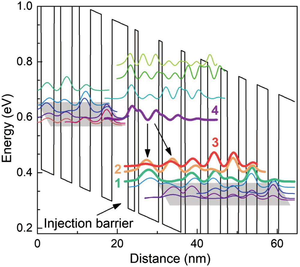
Figure 1.Conduction band diagram and the relevant wave functions of the active core under an applied electric field of 60 kV/cm.
The distribution of electrons in subbands locating below state 4 in one period conforms to the quasi-equilibrium Fermi statistics. When the applied electric field is small, the lower subband may undergo stronger thermal backfilling of electrons from the injection region of the next stage, which reduces the population inversion between states 4 and 2, and the transition is more likely to occur between states 4 and 3. Figure 2 shows the electroluminescence (EL) spectrum measured at a sub-threshold current, which reveals a strong gain peak and a weak gain peak due to transitions from states 4 to 3 and states 4 to 2, respectively. With the increasing applied electric field, the gain peak shifts to higher energy due to the Stark effect[17]. The large dynamic range of the applied electric field and the broad gain spectrum make it possible to realize single-mode dual-wavelength QCL by integrating two DFB gratings with different periods on the upper waveguide. Based on the EL spectrum, is selected near the gain peak of the transition from state 4 to 3, and is blue shifted about relative to the gain peak position. Figure 3 shows the diagram of the superposed DFB grating dual-wavelength QCL. Although two gratings with different periods are stacked together, the frequency selection of each grating is independent, as shown in Ref. [15]. The insert of Fig. 3 is the scanning electron microscope (SEM) image of the dual-period superposed gratings. The influence of the grating duty cycle () on the coupling coefficient () for the two wavelengths is calculated by the finite element method and shown in Fig. 4. Obviously, with the same duty cycle, is smaller than because is inversely proportional to wavelength[18]. In order to obtain similar coupling coefficients, the grating morphology was constructed by changing the dose of the two exposures, as used in Ref. [19]. In our design, the duty cycle () for is 0.5, and for ; the corresponding coupling coefficients are and , respectively.
![]()
Figure 2.EL spectrum measured at a sub-threshold current.
![]()
Figure 3.Concept design of superposed DFB grating dual-wavelength QCL. Inset: SEM image of the dual-period superposed gratings.
![]()
Figure 4.Coupling coefficient (κ) varies with the grating duty cycle (σ) for the two wavelengths. The insets show the calculated modal profiles of λ1 emission with σ = 0.5 (right) and λ2 emission with σ = 0.4 (left), respectively.
The QCL wafer was grown on a semi-insulating InP substrate by solid-source molecular beam epitaxy (MBE). The entire structure starting from the semi-insulating InP substrate was arranged as follows: 0.2 µm highly doped (Si, ) contact layer, 5 µm low-doped (Si, ) bottom InP cladding layer, QCL active core, and 0.3 µm low-doped (Si, ) upper confinement layer. Different from the traditional single-period grating, a grating with the period of was exposed in the InGaAs upper confinement layer by holographic lithography, and then another grating with the period of was superposed on it. The dual-period gratings were formed by one-time wet chemical etching. Following the fabrication of the superposed grating, a 3 µm low-doped (Si, ) upper InP waveguide, a 0.2 µm gradually doped (Si, from to ) InP layer, and a 0.6 µm highly doped (Si, ) InP contact layer were regrown in sequence as the upper cladding by metal organic vapor phase epitaxy (MOVPE). The wafer was then processed into a 10-µm-wide double-channel ridge waveguide by optical photolithography and wet chemical etching[20]. Following that, the epitaxial wafer was loaded in the MOVPE system for semi-insulating InP (Fe) regrowth to improve the lateral heat dissipation of the device. The fabrication process of the planar-electrode device was the same as that in Ref. [16]. Finally, the processed wafer was cleaved to 2 mm long laser bars. A high-reflectivity (HR) coating consisting of (200/10/100/10/250 nm) was deposited on the rear facet of the device by electron beam evaporation. To further improve the heat dissipation, all lasers were mounted epi-side down on patterned AlN submounts and copper heatsinks using indium solder and wire bonded.
3. Device Characterization and Discussion
The laser was mounted on a thermoelectric cooler to control the heatsink temperature. All measurements were performed in CW operation. The output power was measured by a calibrated thermopile detector placed in front of the laser, and the emitting spectra were measured by a Fourier transform infrared (FTIR) spectrometer with a resolution of .
Detailed spectral analysis was performed in CW operation at 20°C by changing the injection current, as shown in Fig. 5(a). The threshold current () of the laser is about 0.45 A. When the injection current is less than , only a single-mode is realized. With increasing current, the peak is tuned from to (7.608–7.617 µm), corresponding to a current tuning coefficient of , while single-mode is achieved when the current is greater than . As the current is increased up to 0.8 A, the peak is tuned from to (7.061–7.068 µm), with a current tuning coefficient of . When the injection current varies between and , both and exist simultaneously. With the increasing injection current, the light intensity of gradually decreases, and the light intensity of gradually increases. The reason for the wavelength evolution behavior is the Stark shift of the gain peak at higher injection currents (bias voltages)[17]. Figure 5(b) provides the typical spectra for the and emission at the currents of and , respectively. For both wavelengths, single-mode emission with side-mode suppression ratio (SMSR) above 25 dB is achieved.
![]()
Figure 5.(a) Optical spectra measured at various currents at 20°C in CW mode. (b) Single-mode spectra of the 7.61 µm and 7.06 µm emission at the currents of 1.2Ith and 1.7Ith, respectively, with SMSR above 25 dB.
Figure 6(a) displays the light-current-voltage (L-I-V) characteristics of the dual-wavelength QCL in CW operation. The three colored areas under the 20°C L-I curve indicate the injection current ranges of , (>1.27–1.66)Ith, and , where the device is emitting a single-mode , two-mode and , and a single-mode , respectively. We can see that the slope of the L-I curve changed slightly near , which is due to the coexistence of and with increasing current (bias voltage). For the HR-coated device with a ridge width of 10 µm and a cavity length of 2 mm, maximum optical powers of above 30 mW and 75 mW can be achieved at 20°C for single-mode and single-mode , respectively. At 10°C, maximum optical powers of about 40 mW and 100 mW can be obtained for single-mode and single-mode , respectively. Figure 6(b) shows the measured emission spectra of single-mode (upper panel) and single-mode (lower panel) from 10°C to 40°C with a 5°C step. In order to show the peak shift with temperature clearly, the plotted spectral intensities have been normalized. The peak wavelength of the emission tuned from 1315.47 to (7.602–7.629 µm), and the emission tuned from 1417.18 to (7.056–7.077 µm), with tuning coefficients of about and for and , respectively, as shown in the insets of Fig. 6(b). These experimental results indicate that with a carefully designed active region structure combined with two superposed DFB gratings of different periods, coaxial single-mode emission at two different wavelengths can be realized only by adjusting the injection current (bias voltage). Moreover, it is worth noting that room temperature CW operation is also advantageous to obtain a narrow emission linewidth, since line broadening due to thermal chirping in pulsed-mode operation can be prevented.
![]()
Figure 6.(a) Light-current-voltage (L-I-V) curves of the dual-wavelength QCL measured at 10°C and 20°C in CW mode. The three colored areas under the 20°C L-I curve correspond to three different injection current ranges with different lasing modes. (b) Temperature-dependent spectra of single-mode λ1 (upper panel) and single-mode λ2 (lower panel) measured from 10°C to 40°C; the insets show the linear tuning of the peak wavenumber with temperature.
4. Conclusion
In summary, we present the design and fabrication of a dual-wavelength QCL by optimizing the design of a homogeneous active region and combining superposed DFB gratings. Switching between the two single-mode emissions was realized only by varying the bias voltage. Optical output powers of above 30 mW and 75 mW were obtained in CW mode at 20°C for single-mode emission at 7.61 µm and 7.06 µm, respectively. Room temperature CW operation is important to achieve a narrow emission linewidth because it can avoid the line broadening caused by thermal chirping in pulsed-mode operation. The peak wavelengths of the 7.61 µm and 7.06 µm emission can also be linearly tuned between 10°C and 40°C with tuning coefficients of about and , respectively. Our designed dual-wavelength QCL enables easy switching between the two coaxial single-mode emissions, which can be adopted in any single-path sensing system for multi-species gas detection. Thus, the simple fabrication process and easy wavelength control of our designed dual-wavelength QCL are very promising for developing miniature multi-species gas sensing systems.
References
[1] J. Faist, F. Capasso, D. L. Sivco, C. Sirtori, A. L. Hutchinson, A. Y. Cho. Quantum cascade laser. Science, 264, 553(1994).
[2] Y. Yao, A. J. Hoffman, C. F. Gmachl. Mid-infrared quantum cascade lasers. Nat. Photonics, 6, 432(2012).
[3] M. Razeghi, W. Zhou, S. Slivken, Q. Y. Lu, D. Wu, R. McClintock. Recent progress of quantum cascade laser research from 3 to 12 µm at the center for quantum devices [Invited]. Appl. Opt., 56, H30(2017).
[4] L. J. Mawst, D. Botez. High-power mid-infrared (λ∼3–6 µm) quantum cascade lasers. IEEE Photonics J., 14, 1508025(2022).
[5] R. F. Curl, F. Capasso, C. Gmachl, A. A. Kosterev, B. McManus, R. Lewicki, M. Pusharsky, G. Wysocki, F. K. Tittel. Quantum cascade lasers in chemical physics. Chem. Phys. Lett., 487, 1(2010).
[6] S. Bartalini, M. S. Vitiello, P. De Natale. Quantum cascade lasers: a versatile source for precise measurements in the mid/far-infrared range. Meas. Sci. Technol., 25, 012001(2014).
[7] C. W. Liu, S. Q. Zhai, J. C. Zhang, Y. H. Zhou, Z. W. Jia, F. Q. Liu, Z. G. Wang. Free-space communication based on quantum cascade laser. J. Semicond., 36, 094009(2015).
[8] Q. Y. Lu, Y. Bai, N. Bandyopadhyay, S. Slivken, M. Razeghi. 2.4 W room temperature continuous wave operation of distributed feedback quantum cascade lasers. Appl. Phys. Lett., 98, 181106(2011).
[9] F. M. Cheng, J. C. Zhang, Y. J. Guan, P. C. Yang, N. Zhuo, S. Q. Zhai, J. Q. Liu, L. J. Wang, S. M. Liu, F. Q. Liu, Z. G. Wang. Ultralow power consumption of a quantum cascade laser operating in continuous-wave mode at room temperature. Opt. Express, 28, 36497(2020).
[10] F. Xie, C. G. Caneau, H. P. LeBlanc, M. T. Ho, J. Wang, S. Chaparala, L. C. Hughes, C. E. Zah. High power and high temperature continuous-wave operation of distributed Bragg reflector quantum cascade lasers. Appl. Phys. Lett., 104, 071109(2014).
[11] P. Q. Liu, K. Sladek, X. J. Wang, J.-Y. Fan, C. F. Gmachl. Single-mode quantum cascade lasers employing a candy-cane shaped monolithic coupled cavity. Appl. Phys. Lett., 99, 241112(2011).
[12] B. Meng, J. Tao, X. H. Li, Y. Q. Zeng, S. Wu, Q. J. Wang. Tunable single-mode slot waveguide quantum cascade lasers. Appl. Phys. Lett., 104, 201106(2014).
[13] K. Fujita, S. Jung, Y. Jiang, J. H. Kim, A. Nakanishi, A. Ito, M. Hitaka, T. Edamura, M. A. Belkin. Recent progress in terahertz difference-frequency quantum cascade laser sources. Nanophotonics, 7, 1795(2018).
[14] J. Jagerska, P. Jouy, A. Hugi, B. Tuzson, H. Looser, M. Mangold, M. Beck, L. Emmenegger, J. Faist. Dual-wavelength quantum cascade laser for trace gas spectroscopy. Appl. Phys. Lett., 105, 161109(2014).
[15] F. Kapsalidis, M. Shahmohammadi, M. J. Suess, J. M. Wolf, E. Gini, M. Beck, M. Hundt, B. Tuzson, L. Emmenegger, J. Faist. Dual-wavelength DFB quantum cascade lasers: sources for multi-species trace gas spectroscopy. Appl. Phys. B, 124, 107(2018).
[16] Y. J. Guan, L. J. Wang, N. Zhuo, J. C. Zhang, S. Q. Zhai, J. Q. Liu, S. M. Liu, F. Q. Liu. Dual-wavelength switchable, mid-infrared quantum cascade laser with two shallow-etched distributed Bragg reflectors. Opt. Express, 29, 39376(2021).
[17] A. Bismuto, R. Terazzi, M. Beck, J. Faist. Electrically tunable, high performance quantum cascade laser. Appl. Phys. Lett., 96, 141105(2010).
[18] H. Kogelnik, C. V. Shank. Coupled-wave theory of distributed feedback lasers. J. Appl. Phys., 43, 2327(1972).
[19] Q. Y. Lu, W. Zhang, L. J. Wang, J. Q. Liu, L. Li, F. Q. Liu, Z. G. Wang. Holographic fabricated photonic-crystal distributed-feedback quantum cascade laser with near-diffraction-limited beam quality. Opt. Express, 17, 18900(2009).
[20] A. Evans, S. R. Darvish, S. Slivken, J. Nguyen, Y. Bai, M. Razeghi. Buried heterostructure quantum cascade lasers with high continuous-wave wall plug efficiency. Appl. Phys. Lett., 91, 071101(2007).

Set citation alerts for the article
Please enter your email address
© Copyright 2018-2021 | Chinese Laser Press. All Rights Reserved 沪ICP备15018463号-20