Yang Wang1,2,†, Weiqiang Wang1,5,†,*, Zhizhou Lu3,†..., Xinyu Wang1,2, Long Huang1,2, Brent E. Little1, Sai T. Chu4, Wei Zhao1,2 and Wenfu Zhang1,2,6,*|Show fewer author(s)
1State Key Laboratory of Transient Optics and Photonics, Xi’an Institute of Optics and Precision Mechanics, Chinese Academy of Sciences, Xi’an 710119, China
2University of Chinese Academy of Sciences, Beijing 100049, China
3Chongqing United Microelectronics Center (CUMEC), Chongqing 401332, China
4Department of Physics and Materials Science, City University of Hong Kong, Hong Kong, China
Yang Wang, Weiqiang Wang, Zhizhou Lu, Xinyu Wang, Long Huang, Brent E. Little, Sai T. Chu, Wei Zhao, Wenfu Zhang, "Hyperbolic resonant radiation of concomitant microcombs induced by cross-phase modulation," Photonics Res. 11, 1075 (2023)
Copy Citation Text
A high-quality optical microcavity can enhance optical nonlinear effects by resonant recirculation, which provides a reliable platform for nonlinear optics research. When a soliton microcomb and a probe optical field are coexisting in a micro-resonator, a concomitant microcomb (CMC) induced by cross-phase modulation (XPM) will be formed synchronously. Here, we characterize the CMC comprehensively in a micro-resonator through theory, numerical simulation, and experimental verification. It is found that the CMCs spectra are modulated due to resonant radiation (RR) resulting from the interaction of dispersion and XPM effects. The group velocity dispersion induces symmetric RRs on the CMC, which leads to a symmetric spectral envelope and a dual-peak pulse in frequency and temporal domains, respectively, while the group velocity mismatch breaks the symmetry of RRs and leads to asymmetric spectral and temporal profiles. When the group velocity is linearly varying with frequency, two RR frequencies are hyperbolically distributed about the pump, and the probe light acts as one of the asymptotic lines. Our results enrich the CMC dynamics and guide microcomb design and applications such as spectral extension and dark pulse generation.
1. INTRODUCTION
Cross-phase modulation (XPM) is a common optical nonlinear effect while two optical fields co-propagate in nonlinear optical media, which arises from optical intensity-related nonlinear phase shift [1,2]. For a dispersion-free medium, the probe light will obtain identical frequency chirps but opposite in sign on the rising and falling edges of the pump pulse [3]. Therefore, symmetric optical frequencies are generated around the two sides of the probe field. In temporal domain, the waveform of pump pulse is duplicated. This phenomenon has been widely extended in wavelength conversion in communication systems [4], synchronization of two mode-locked lasers [5], and quantum nondemolition measurements [6]. Considering the dispersion characteristic of an actual optical medium, the symmetries of the temporal waveform and spectral envelope of the XPM effect may be broken due to the influence of group velocity dispersion (GVD) and group velocity mismatch (GVM) effects. Meanwhile, the interaction length reduces in the travelling-wave experiments due to the walk-off effect, which weakens the interaction strength of XPM effect [7,8].
Sign up for Photonics Research TOC. Get the latest issue of Photonics Research delivered right to you!Sign up now
The optical field interaction length can be improved in an optical cavity through resonant recirculation. The recently developed high-quality micro-resonators provide an ideal platform for nonlinear optics researches [9–11]. A typical application is the generation of soliton microcomb (SMC) [12–18], which promotes the development of soliton physics, such as the Raman self-frequency shift [19,20], Cherenkov radiation [21–23], soliton crystals [24–26], breathing solitons [27–29], and Stokes solitons [30]. When multiple optical fields are concomitant in a micro-resonator, a steady state can be reached through periodic interaction. Once an SMC is formed, the index of the micro-resonator is periodically modulated by solitons through Kerr effect. When a probe light is coupled into the micro-resonator simultaneously, it would interact with SMCs circularly and results in high-efficiency concomitant microcomb (CMC) formation. The CMC has the same repetition rate as the SMC, which has been employed to extend the spectral range of an SMC [31] and dark pulses formation [32]. Dual orthogonal microcombs are also experimentally realized by injecting an orthogonal polarized probe light [33]. However, in a micro-resonator, the influence of GVD, GVM, and XPM effects on the CMC generation is still not systematically analyzed.
In this paper, the characteristic of the CMC in a micro-resonator is theoretically, numerically, and experimentally studied, where an SMC is used as the pump pulse. We analyze the linear stability of the probe light and deduce the phase matching condition (PMC) of the light field evolution considering both dispersion and XPM effect. The CMC shows modulated spectral structure under the action of XPM. When the pump pulse and probe light have different group velocity, the symmetry of the CMC is broken in both of temporal and frequency domains due to the influence of GVD and GVM effects. In addition, we found a universal law of CMCs that the two-frequency wring distribution of the CMC has a hyperbolic characteristic.
2. THEORY
A. Principle and Model
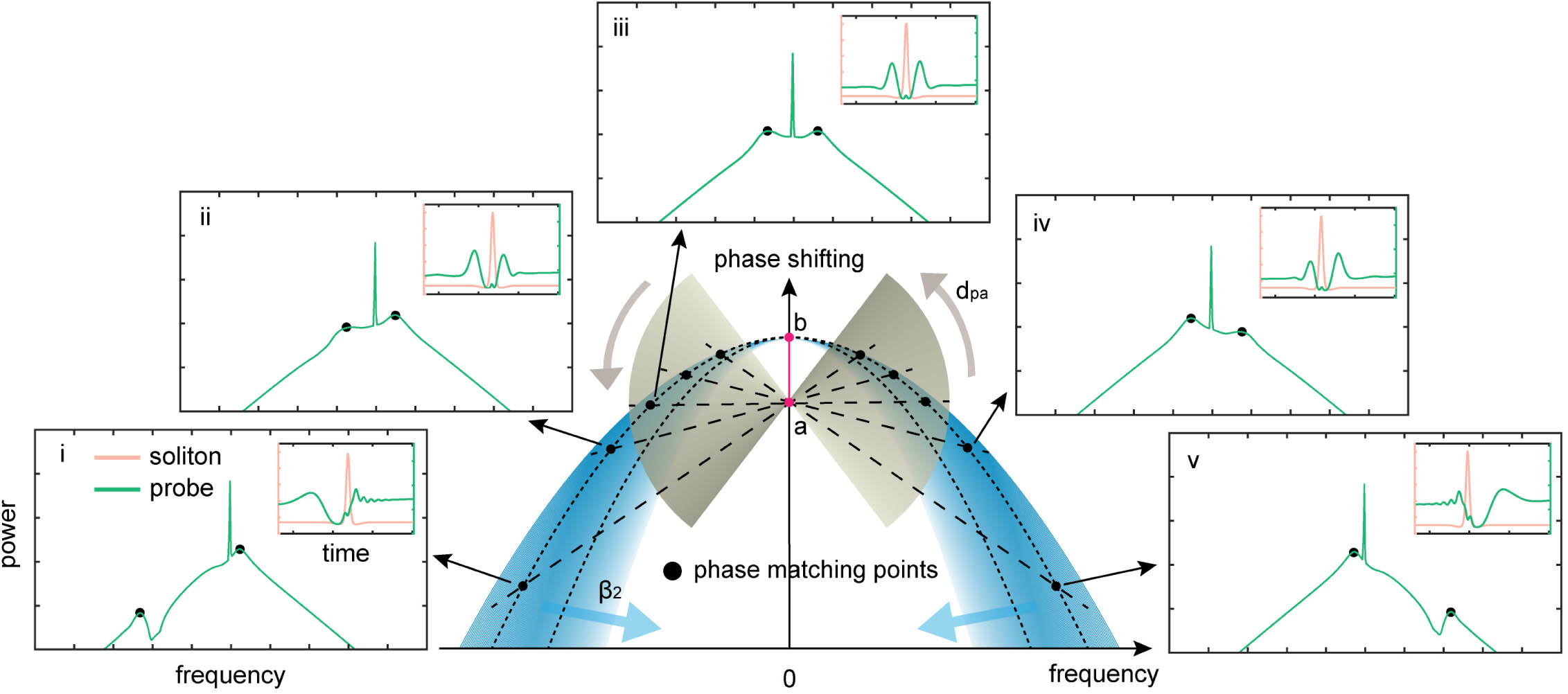
Figure 1 schematically shows the influence of GVD and GVM on the CMC formation. When a continuous wave (CW) probe field and a pump pulse coexist in a micro-resonator, the probe light is subjected to a nonlinear phase shift due to the self-phase modulation and XPM (red line in Fig. 1). For a pump–probe configuration [7], the intensity of the probe wave is much lower than that of the pump, so the nonlinear phase shift is mainly caused by XPM effect. The probe wave experiences modulation instability arising from the interaction of dispersion and XPM effects. Generally, the probe and pump waves have different group velocity in a dispersive waveguide, which results in walk-off effect. The walk-off parameter is indicated by . When a micro-resonator has a standard parabolic dispersion curve, is linearly varying with frequency. The gain peaks of modulation instability, termed as resonant radiations (RRs) [34–37], occur on the intersection points of the dispersion curve and a line crossing the nonlinear phase shift point with a slope of . For example, the RRs were symmetrically distributed about the probe field when . Meanwhile, a symmetric pulse pair is formed around the pump pulse. Otherwise, the symmetry of the CMC is broken when . When is large enough, the CMC would evolve into a dark pulse.
Figure 1.CMC optical field evolution with walk-off parameter. A nonlinear phase shift is added to the probe field (red line). The optimal phase matching frequencies have maximum modulation instability gain, which forms RRs. For a micro-resonator with a standard parabolic dispersion curve, the walk-off parameter is in proportion to the frequency difference between the probe and pump fields. The RRs occur on the intersection points of the dispersion curve and a line across the phase shift point “a” with slope of . And the CMC optical field evolves from a symmetric structure to nearly a single peak spectrum along with the increase of .
To generate a CMC, an SMC is employed as the pump pulse, which is spontaneously formed by driving a micro-resonator using a CW laser, while another CW laser is used as probe light and coupled into the micro-resonator simultaneously. The optical field evolution dynamics can be modeled using the coupled Lugiato-Lefever equations (LLEs) [24], considering the XPM, GVM, and GVD effects simultaneously, where and are the intracavity pump and probe field envelopes, respectively; and are the slow and fast time, respectively; and are the round trip time of the pump and probe fields; and are the phase detuning of the pump and probe from the adjacent resonance frequencies, respectively; and represent the power loss per round trip; and are the power coupling coefficients; and are the second-order dispersion coefficients; is cavity length; and are nonlinearity coefficients; and are the external driving power; is a scaling factor determined by the difference of the phase detuning between the pump and the probe (); is the intracavity backscattering coefficient; the integer is the mode interval of the pump and probe waves; is the free spectral range of the microcavity; and , is the walk-off parameter, where and are the group velocity of the pump and probe, respectively. In Eq. (1), the last term represents the modulated background field arising from the beating signal between the pump and probe optical waves.
B. Linear Stability Analysis and Phase Matching Condition
The CMC arises from the frequency chirps induced by the intensity related nonlinear index modulation. The stable soliton solution can be expressed as , where is the soliton amplitude, is the pulse width factor, and is the carrier phase. Frequency chirps imposed on the probe light can be expressed as
In order to explore the influence of the GVD effect and GVM effect on the CMC, the PMC is analyzed through perturbation theory [34–38]. and are the homogeneous steady-state (HSS) solutions of Eqs. (1) and (2), respectively. As the intensity of pump is much higher than that of the probe light, the background modulation term of Eq. (1) is neglected. The HSS solution of the probe field is where and .
A perturbation is imposed on the HSS of probe field, . Taking no account of the transmission loss , the perturbation term satisfies the following equation: where “ * ” denotes complex conjugation.
Equation (5) has a solution with form of , where and are the wavenumber and angular frequency difference between the perturbation and probe light, respectively; in addition, and are Stokes and anti-Stokes free wave amplitudes, respectively. To obtain nonzero solutions of Eq. (5), the dispersion relationship should satisfy
The frequencies around the optimal phase matching points [i.e., ] can obtain maximum nonlinear gain. As the intensity of the probe light is much lower than the pump pulse, the self-phase modulation term is neglected, and the PMC can be expressed as
The product of the two solutions of Eq. (7) can be expressed as
It clearly shows the product is only related to the micro-resonator parameters and pump condition. When is a constant in the considered frequency range, the product of frequency differences between the probe light and the two RRs would be a constant.
The angular frequency difference between the pump and probe light is denoted as , the angular frequency difference between the RRs and the pump light is , and for a certain frequency range where the group refractive index is linearly varying. Considering the relationship , the optimal phase matching frequencies related with can be further expressed as
Equation (9) shows is a hyperbolic function about . When is linearly varying in a certain frequency range, two RRs are symmetrically distributed on the two sides of the pump laser. The RRs have the asymptotic lines of , i.e., the probe light acts as one of the asymptotic lines of .
3. EXPERIMENTAL RESULTS AND DISCUSSION
In our experiments, the core device is an add–drop micro-ring resonator [MRR; see Fig. 2(c)], which is encapsulated in a butterfly package with a thermo-electric cooler (TEC) for operation temperature control [18,24]. The MRR has a free spectral range of 49 GHz and quality factor of , and the anomalous dispersion characteristic supports bright SMC formation. The calculated group velocity of the MRR is shown in Fig. 2(d), which is approximatively linearly varying in the frequency range of bands. Figure 2(a) shows the schematic diagram of the CMC generation experiment. Two tunable narrow linewidth lasers are used as pump and probe lasers, which are amplified by two commercial erbium-doped fiber amplifiers (EDFAs), respectively.
Figure 2.Experimental setup and results. (a) Schematic diagram of the experimental setup. (b) Measured optical spectra when the probe field has slower, similar, and faster group velocity, where the SMCs are used as pump for CMC generation. (c) Top view of MRR. (d) Calculated group velocity of the MRR.
SMCs are generated using the well-developed laser assisted thermal balance scheme [18,39]. Less than 4% energy of the auxiliary light is reflected back by the MRR and used as probe field for CMC generation. To observe the CMC, perfect soliton crystals [24] are employed in our experiments, which ensures that the CMC occupies different resonant modes with the SMC for better comparison. Figure 2(b) shows the optical spectra of the CMCs. To maximally eliminate the influence of GVD and GVM, the probe field is set to the neighboring resonant modes of the pump. A CMC with nearly symmetric optical spectrum is observed as shown in region (ii) of Fig. 2(b). When the probe field is away from the pump laser, the optical spectral symmetry of the CMC is broken due to the GVD and GVM of the MRR [regions (i) and (iii) of Fig. 2(b)]. The positions of RRs are marked in the figure. The products of frequency differences between the probe light and the RRs are , , and for the three cases, respectively. It is consistent with the theoretical value of according to Eq. (8).
To verify our theory and investigate the temporal profile of the CMC, coupled LLEs are employed for simulation, which are numerically calculated using the fourth-order Runga–Kutta and split-step Fourier methods. During the simulation, both pump and probe powers are set to 400 mW, and the other parameters are consistent with the experimental conditions (see Appendix C). The frequencies of the probe light are set at 195.2, 192.1, and 187.3 THz, where the walk-off parameter is positive, 0, and negative, respectively. When the probe and pump optical fields have the same group velocity, i.e., the pump of SMC and probe light locating at the same resonant modes, the CMC has a symmetric spectral envelope. In temporal domain, a dual-peak pulse is formed, where the two peaks symmetrically locate at the rising and falling edges of pump pulse, respectively [Fig. 3(b)]. When is unequal to 0, the symmetry of the CMC is broken in both spectral and temporal domains due to the GVD and GVM effects. When is large enough, the waveform of the CMC evolves into dark pulse, which corresponds to the generation of dark-bright soliton pairs in Ref. [32]. For a positive , the probe field has larger group velocity, and the interaction of XPM mainly occurs at the falling edge. Therefore, a dark pulse forms around the falling edge of the pump pulse [Fig. 3(a)], while for , the probe light has slower group velocity and the interaction of XPM mainly occurs at the rising edge, where a dark pulse forms around the rising edge of the pump pulse [Fig. 3(c)]. As a comparison, Figs. 3(d)–3(f) show the experimental results, whose spectrum envelopes are consistent with the theoretical results. To be clear, similar to the spectrum in region (ii) of Fig. 2(b), some weak secondary combs of the soliton crystal in Figs. 3(b) and 3(e) occurred due to the fluctuation of pulse power in the temporal domain, which occupy the same resonant modes as the CMC, and are difficult to distinguish unless using an ultra-high resolution optical spectrum analyzer.
Figure 3.Temporal and spectral characteristics of CMC. (a)–(c) Calculated waveforms and spectra of CMC when are positive, 0, and negative, respectively. (d)–(f) Measured optical spectra of CMC.
In order to intuitively observe the optical spectrum characteristics of the CMC under the condition of different GVD and GVM, the coupled LLEs are calculated by sweeping the frequency of probe light. During the simulations, the walk-off parameter is linearly varying with the frequency difference between the probe and pump fields. Figures 4(a) and 4(b) show the waterfall diagram of the CMC using the frequencies of the probe and pump waves as references, respectively. Meanwhile, the RRs are also plotted according to the PMC based on Eqs. (7) and (9), which overlap well with the RRs of the simulation results. The frequencies of RRs are symmetric about the pump laser, and the probe light is one asymptotic line of the RRs. Five typical spectra of CMC are shown in Fig. 4(c). Along with the increase of , the symmetry of the CMC spectra is broken, and one of spectral wings far away from the probe attenuates dramatically. When is larger than , one of the frequency “wings” is too weak to observe. Therefore, the CMC represents a single spectral peak and forms a dark pulse in temporal domain.
Figure 4.Spectral characteristic of CMC. (a) and (b) show the optical spectral evolution along with , which use the frequencies of probe and pump fields as the reference, respectively. (c) Typical optical spectra of CMC when equals , , 0, and , respectively.
It should be clear that the theoretical analysis and simulations are under the condition that the phase detuning , comprehensive loss , and driving power Pin,a are constants. As long as GVD and GVM exist, the symmetry of the CMC will be broken. The temporal and spectral domain characteristics of CMC are highly related with the micro-resonator property and pump condition. In addition, it is well known that integrated dispersion is often used to calculate the position of dispersive radiation [21,31,32], where only the dispersion effect is considered and the influence of nonlinear effects (such as XPM) on PMCs is ignored. Therefore, compared to the method of calculating integrated dispersion , the analytical method adopted in this paper has higher accuracy. It is also worth noting that here we only consider probe light co-propagating with pump light through the weak backscattering effect. For strong backscattering, however, the CMC may cease to exist due to the annihilation of soliton states and may also be transformed into breathing solitons. In another work, we discuss in detail some of the dynamics of the self-oscillation microcomb in the case of strong backscattering [29].
4. CONCLUSION
In conclusion, we characterized the CMC comprehensively by theoretical modeling, numerical simulation, and experimental verification. The expression of PMC for CMC is precisely derived, and a more universal law about XPM-induced CMC is discovered. The CMCs are generated in a micro-resonator using SMCs as the pump and are modulated in both temporal and spectral domains. The modulation is highly influenced by the GVD and GVM effects. The symmetry of the CMC is broken when the probe light and pump have different group velocity. The products of frequency differences between the probe light, and two wrings of CMC are a constant when the group index is linearly varying. Using the pump as reference, the RRs show hyperbolic distribution. Meanwhile, the wing far away from the probe field attenuates much faster, which would be too weak to observe when is large enough. Phenomenally, the CMC becomes a single frequency wing structure, which shows a dark pulse in temporal domain. In fact, it can be inferred from the expression of the PMC that the number of RR peaks will be larger when higher order dispersion is considered and that any odd-order dispersion will result in the symmetry breaking of RR. Our results reveal the steady-state characteristics of a CMC, which enrich the nonlinear optical processes in a dispersion micro-resonator.
Acknowledgment
Acknowledgment. The authors thank Mu-Long Liu, Xiao-Hong Hu, Ming-Ran Zhang, Wei-Chen Fan, and Min Wang for the helpful discussions. The authors thank Chao Liu for providing the high-resolution image of the microcavity.
APPENDIX A: HOMOGENEOUS STEADY-STATE SOLUTION AND FREQUENCY CHIRPS
The HSS solutions of the coupled LLEs are and , respectively, where . As the modulated background field is much weaker than the soliton intensity, we ignore the last item of Eq. (1) in our analysis. The intensity of pump and probe fields can be solved: where , , , and .
To study the probe field spectral broadening, the nonlinear phase shift and frequency chirps caused by the XPM effect should be analyzed. We assume the pump pulse is a stable SMC, which can be expressed as
When only the XPM term is considered, the general solution of Eq. (2) at is
A time-dependent nonlinear phase shift is imposed to the probe field per circle around the microcavity,
The frequency chirps caused by the phase shift are defined as
Combining the Eqs. (A3), (A5), and (A6), the frequency chirp of the probe field is expressed as Eq. (3).
We numerically calculate the frequency chirps of the probe field for intuitive observation. First, GVD and GVM effects are not considered. Some simulation parameters are set as , , , , and . Figure 5(a) shows the temporal profile of the pump pulse obtained by numerical simulation, and Fig. 5(b) shows the frequency chirps calculated according to the Eqs. (A5) and (A6). Figures 5(c) and 5(d) show the temporal and spectral profiles of the probe field, respectively. The optical spectrum (green) is numerical results based on the coupled LLEs, while the analytic spectrum is indicated by the black line, and they agree very well with each other. The multi-peak structure is caused by constructive or destructive interference.
Figure 5.Steady-state characteristics of the CMC. (a) Steady-state pump pulse (soliton pulse). (b) Frequency chirps induced by pump pulse by XPM effect. (c) Temporal waveform of steady-state CMC. (d) Optical spectrum of steady-state CMC. The modulated spectral envelope is caused by the constructive or destructive interference.
APPENDIX B: PERTURBATION THEORY AND FURTHER VERIFICATION
In order to explore the influence of the GVD and GVM effects on the spectrum of the probe field, the PMC is analyzed using perturbation theory [34–38]. The HSS probe field with perturbation is expressed as
Substituting Eq. (B1) into Eq. (2), the HSS probe field with perturbation satisfies the following equation:
For a high-quality micro-resonator, we ignore the loss term and higher-order terms based on linear perturbation approximation. The perturbation field satisfies Eq. (5), where . The solution of Eq. (5) has the following form:
In addition, the complex conjugate form of the solution is
Substituting Eq. (B3) and Eq. (B4) into Eq. (5), we obtain where is a unit matrix, eigenvector , and B is the coefficient matrix,
To obtain nonzero solution of , the following condition needs to be satisfied:
The dispersion relation of the RR process can be obtained as Eq. (6). The energy peaks of RRs correspond to the PMC [i.e., ]; therefore, the PMC can be expressed by Eqs. (7) and (9). Interestingly, is a hyperbolic function about under suitable conditions.
Next, we investigate the influence of the GVD and GVM effect on the CMC using the above theoretical analysis and numerical simulation according to the coupled LLEs. For a general condition, the pump is the CW field with white noise, where is the average intensity of the pump and represents the noise signal with a random distribution in the range (0,1). In our simulation, .
Figures 6(a) and 6(b) show the temporal waveform and spectrum of the CMC under XPM effect with only GVD effect being considered. Although the generated spectra are very weak, two symmetric RRs are still clearly observed. While the pump is high power pulses, the new generated frequency components are enhanced and become a CMC as shown in Figs. 6(c) and 6(d), while the position of the RRs does not vary with pump power. Next, we consider both GVD and GVM effects. Figures 6(e) and 6(f) show the corresponding temporal waveform and spectrum, where the symmetry of the CMC spectrum is broken, and the RRs are no longer symmetrically distributed around the probe field. Unsurprisingly, the position of RRs is still not changed as shown in Figs. 6(g) and 6(h) for high pump power operation.
Figure 6.Effect of GVD and GVM on probe field. (a), (c), (e), (g) are the temporal domain distribution of pump field and probe field, and (b), (d), (f), (h) are the spectra of probe field. In (a), (b), (e), (f), the pump field is a noisy CW, and in (c), (d), (g), (h), the pump field is an SMC. In (a)–(d), only GVD effect is considered, and in (e)–(h), both GVD and GVM effects are considered simultaneously.
Figure 7.Influence of GVD and GVM effects on XPM. (a) and (b) show the waterfall diagram of the spectrum of the probe field, which takes the wavelength of probe and pump light as the reference, respectively, where the black solid line represents the RR position.
[38] L. Bahloul, L. Cherbi, A. Hariz, M. Tlidi. Temporal localized structures in photonic crystal fibre resonators and their spontaneous symmetry-breaking instability. Philos. Trans. R. Soc. A, 372, 20140020(2014).
Yang Wang, Weiqiang Wang, Zhizhou Lu, Xinyu Wang, Long Huang, Brent E. Little, Sai T. Chu, Wei Zhao, Wenfu Zhang, "Hyperbolic resonant radiation of concomitant microcombs induced by cross-phase modulation," Photonics Res. 11, 1075 (2023)