
Hongbo Liu. Electrocaloric effect enhanced thermal conduction of a multilayer ceramic structure[J]. Chinese Physics B, 2020, 29(8):
- Chinese Physics B
- Vol. 29, Issue 8, (2020)
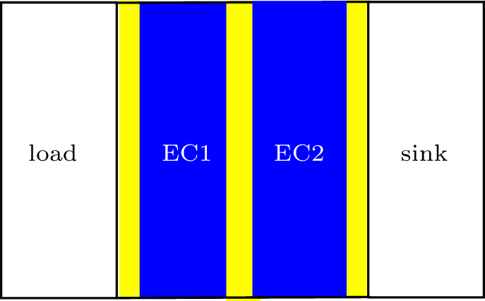
Fig. 1. The designed multi-layer structure. From left to right, there are cooling load, electrode, ferroelectric ceramic layer EC1, electrode, ferroelectric ceramic layer EC2, electrode, and heat sink.
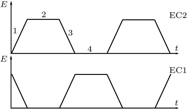
Fig. 2. The sequential electric fields applied to each EC units.
Fig. 3. The transferred heat Q as a function of the temperature difference between load and heat sink (T load – T sink). Here, case 1 is the transferred heat of the proposed MLCC with EC effect, case 2 is the transferred heat of the same structure without EC effect, and case 3 is the transferred heat of the same structure replacing EC layers with Ni metal.

Set citation alerts for the article
Please enter your email address
© Copyright 2018-2021 | Chinese Laser Press. All Rights Reserved 沪ICP备15018463号-20