• Chinese Optics Letters
  • Vol. 19, Issue 6, 060009 (2021)
Jinhua Zhao1、*, Xueshuai Jiao1, Yingying Ren2, Jinjun Gu1, Sumei Wang1, Mingyang Bu1, and Lei Wang3
Author Affiliations
  • 1School of Science, Shandong Jianzhu University, Jinan 250101, China
  • 2Shandong Provincial Engineering and Technical Center of Light Manipulations & Shandong Provincial Key Laboratory of Optics and Photonic Device, School of Physics and Electronics, Shandong Normal University, Jinan 250014, China
  • 3School of Physics, Shandong University, Jinan 250100, China
  • show less
    DOI: 10.3788/COL202119.060009 Cite this Article Set citation alerts
    Jinhua Zhao, Xueshuai Jiao, Yingying Ren, Jinjun Gu, Sumei Wang, Mingyang Bu, Lei Wang. Lithium niobate planar and ridge waveguides fabricated by 3 MeV oxygen ion implantation and precise diamond dicing[J]. Chinese Optics Letters, 2021, 19(6): 060009 Copy Citation Text show less

    Abstract

    We report on the fabrication and optimization of lithium niobate planar and ridge waveguides at the wavelength of 633 nm. To obtain a planar waveguide, oxygen ions with an energy of 3.0 MeV and a fluence of 1.5×10¹⁵ ions/cm2 are implanted in the polished face of LiNbO3 crystals. For planar waveguides, a loss of 0.5 dB/cm is obtained after annealing at 300°C for 30 min. The ridge waveguide is fabricated by the diamond blade dicing method on optimized planar waveguides. The guiding properties are investigated by prism coupling and end-face coupling methods.

    1. Introduction

    Lithium niobate (LiNbO3, LN) is an attractive functional crystal material with outstanding optical properties. In past years, research into the LN crystal has intensified, and it is widely used in the field of integrated optics[14]. It continues to attract research interest attributed to the critical status of the LN platform in integrated optical systems, which can be compared to “Si in integrated circuit”. One of the representative achievements is the emergence of LN on insulator (LNOI) technology, which can be an alternative platform for integrated optical applications[3]. The waveguide is the basic component for the device of photonic integrated circuits (PICs). Based on this, the researches on LN waveguides enable the industrial application. In this work, we investigate the optical properties of planar and ridge waveguides in LN crystals.

    Since ion implantation has become an effective and relatively mature waveguide manufacturing tool in the past decades[5,6], it has stimulated researchers’ interest in using ion implantation to make waveguide structures on nonlinear optical materials. On the one hand, LN has been proven to be a good material for optical waveguides produced by mega electron volt (MeV) ion implantation[68]. On the other hand, some medium-mass ions[810] have been proven to be a good ion implantation choice for forming high-quality waveguides. As reported in previous work[6,9,10], the implantation of oxygen (O) ions has been utilized for waveguide formation in LN crystals. The quality of the waveguide is acceptable for practical application. In this work, the planar waveguide is fabricated on LN crystal by O ion implantation at the energy of 3 MeV, which is one of the medium-mass ions.

    The optical waveguide has become the basic component for electro-optic devices in PICs. In particular, two-dimensional (2D) waveguides[1113] have practical application value due to the ability of efficiently connecting with optical fibers for PICs. At present, channel and ridge shapes are basic structures of 2D waveguides. The ridge waveguide has high index contrast compared to the channel shape. To create the ridge shape in LN, conventionally, wet etching[12] or dry etching[13] has been used. In these methods, there are some disadvantages that cannot be avoided in the experimental setup. Firstly, the mask is necessary in the process of wet etching and most of dry etching, and the fabrication of the mask will increase the cost both in time and financially. Secondly, etching techniques have limitations in different aspects. The wet etching process has a strict requirement for the direction of etching, which can only be applied on the −z face of LN substrates. Dry etching approaches based on direct plasma etching techniques[1416] cannot yield depths larger than 5 µm to obtain a tolerable roughness. Thirdly, the factors of environment pollution exist in wet etching and mask fabrication processes. Fortunately, precision diamond dicing has turned out to be an effective alternative route for ridge structuring[1722]. Precision diamond dicing is a powerful technique for ridge structure formation, and it has been used in some materials successfully, including LN crystals because it offers accurate control of both width and depth through use of different blade parameters. It is worth noting that precise dicing is a quick, reliable, and reproducible technique, allowing the patterning of x-cut or z-cut substrates, indifferently. As reported in Refs. [1721], this approach is generally combined with conventional diffusion, ion exchange, and ion implantation processes to fabricate ridge waveguides. In this work, we show that prominent performances of LN ridge waveguides can be reached by use of O ion implantation and precision dicing. Moreover, the optimum annealing condition is proposed in our experimental arrangement, which also has contributions to the waveguide quality.

    2. Experiment and Details

    The LN crystals used in this work are z-cut with dimensions of 10mm×8mm×1mm, and the top/bottom faces (10mm×8mm) are optically polished. The ridge waveguides in this work are fabricated by two major steps, ion implantation and precise dicing. The details are introduced as follows.

    2.1. Planar waveguide formation and optimization

    To obtain a low loss planar waveguide, O ions at the energy of 3.0 MeV with a fluence of 1.5×10¹⁵ions/cm2 are implanted in the polished face of LN crystals. The implanted process is performed in a 1.7 MV tandem accelerator (located in Peking University) at room temperature. The ion beam was electrically scanned to ensure a uniform implantation over the samples. In order to avoid the channeling effect, the samples were titled 7° off the beam direction. The damage layer is formed in the LN crystals after the implantation process. The optical properties of implanted LN crystals are investigated by prism coupling and end-face coupling arrangements. To operate end-face coupling measurements, the end faces (the input and output faces) of samples are optically polished after the ion implantation process. The post annealing treatment must be applied to obtain a low loss planar waveguide. To find the best annealing condition, we carried out annealing treatments at 200°C (A1), 300°C (A2), 400°C (A3), and 500°C (A4) with the same time of 30 min on four planar waveguide samples separately. The optimized annealing condition is found, and the low loss planar waveguide is fabricated through the ion implantation process.

    2.2. Precise dicing and ridge waveguide formation

    The precise dicing technique is used to carve grooves in LN planar waveguides. This process is completed in Shanghai (Disc DAD323). The important criteria for obtaining an eligible ridge are smooth side walls and little chipping on both the surface and end face. Ridge waveguides with smooth walls and acceptable edges are fabricated by adjusting the dicing conditions. The optimum dicing condition used in this work is that the thickness and diameter of the diamond blade are 23 µm and 56 mm, respectively, the rotation speed is 40,000 r/min, and the moving speed is 0.5 mm/s. The blade is translated along the entire length of the wafer, which is convinced that the precise dicing is an effective and useful tool to fabricate centimeter-long ridge waveguides. The near-field intensity profile and propagation loss of ridge waveguides are measured by the end-face coupling method.

    3. Results and Discussion

    The values of the substrate refractive index (
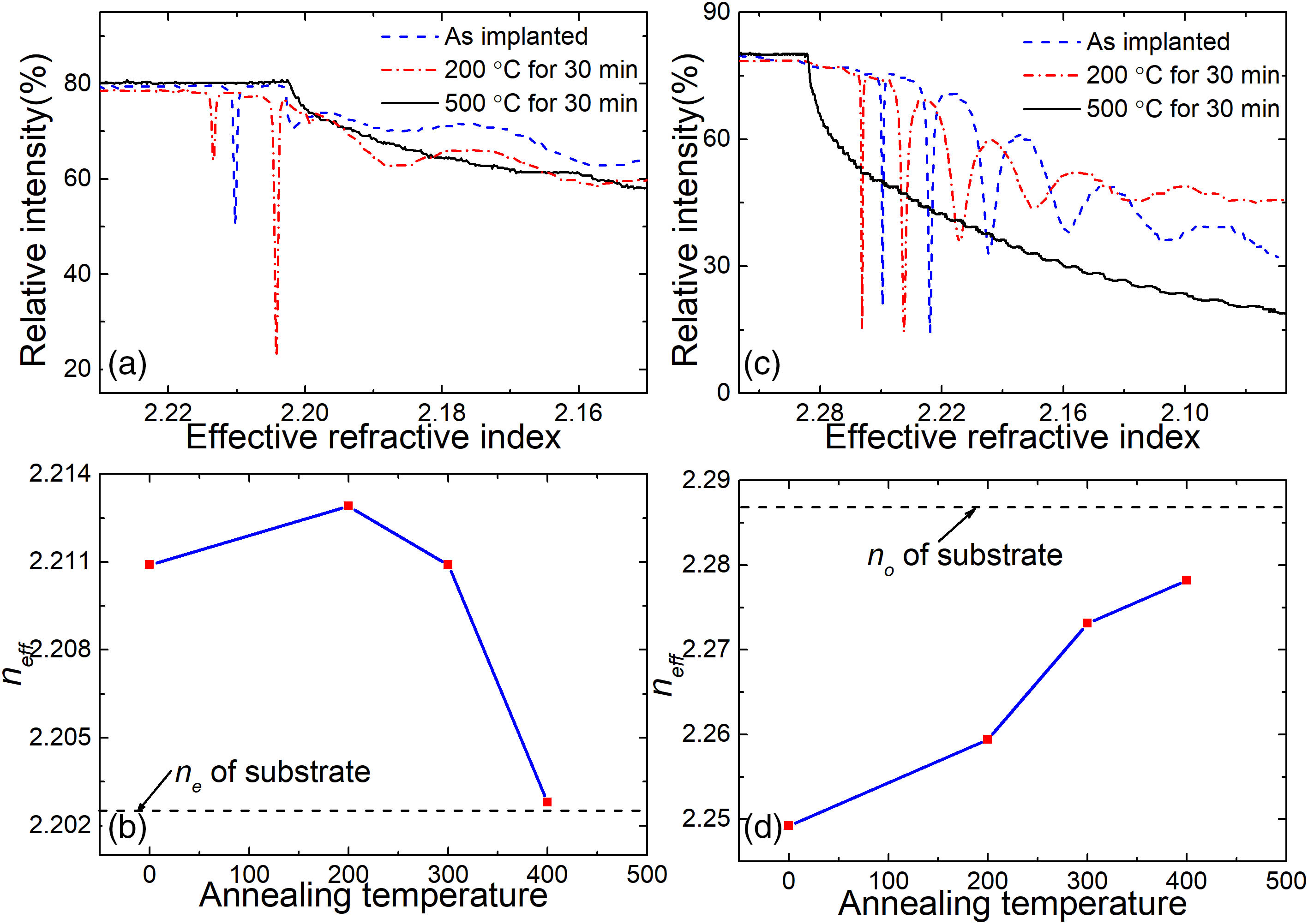
nsub) for extraordinary and ordinary light directions (ne and no) of LN crystals are 2.2028 and 2.2868, separately. The planar waveguides are fabricated by 3.0 MeV O ions implantation. For the planar waveguide, the prism coupling measurement is an effective and intuitive investigation method to obtain the guide mode effective refractive index (neff). In this experimental arrangement, a dip in the curve corresponds to the lack of reflected light originating from the mode excitation in the waveguide. In order to optimize the waveguide quality, annealing treatments from 200 to 500°C are used in LN planar waveguide samples in air atmosphere. We performed a prism-coupling experiment of both transverse magnetic (TM, ne direction) and transverse electric (TE, no direction) polarizations for the O implanted waveguides after each different annealing condition at a wavelength of 633 nm. Figure 1(a) shows the dark mode spectra of the TM polarized light at the wavelength of 633 nm both before and after annealing. It is found that the first dip (TM0 mode) is very sharp, and the neff is higher than nsub, which may be the real guided mode for the as implanted sample. Obviously, the neff of the first guided mode (2.2109) is increased, and the second sharp dip appears after annealing at 200°C for 30 min in air atmosphere. We note that the dips disappear after annealing at 500°C for 30 min. This phenomenon indicates that the properties of the O implanted sample are the same as virgin LN when the annealing temperature is up to 500°C. In other words, the damage or lattice disorder caused by our O implanted condition in the LN crystal could be recovered completely after annealing at 500°C for 30 min. The detail trend of the TM0 modes after different annealing treatments is shown in Fig. 1(b). The corresponding results for TE polarization are depicted in Figs. 1(c) and 1(d). The main feature of the effective refractive indices to be remarked is the ascending-descending trend of the TM0 mode as the annealing temperature increases, whereas the TE0 mode shows monotonic decrease behaviour.

    Measured relative intensity of reflected light from the prism versus the effective refractive index at a wavelength of 633 nm before and after annealing for O implanted planar waveguides: (a) TM polarized light and (c) TE polarized light. Effective refractive indices of the (b) TM0 mode and (d) TE0 mode varying with different annealing temperatures for the same time of 30 min.

    Figure 1.Measured relative intensity of reflected light from the prism versus the effective refractive index at a wavelength of 633 nm before and after annealing for O implanted planar waveguides: (a) TM polarized light and (c) TE polarized light. Effective refractive indices of the (b) TM0 mode and (d) TE0 mode varying with different annealing temperatures for the same time of 30 min.

    The stopping and range of ions in matter (SRIM) 2013[23] is used to calculate the damage per atom (dpa). Figure 2 shows the dpa profile varying with implantation depth. The damage peak position is located at 1.95 µm. The refractive index profile (RIP) is reconstructed by the reflectivity calculation method (RCM)[24] based on the prism coupling measurements and dpa profile. The reconstructed RIPs of O implanted waveguides after annealing at 200°C for 30 min (A1) are illustrated in Fig. 3. As depicted in Fig. 3(a), the waveguide has been formed in extraordinary light direction after the ion implantation process due to the “enhanced-index well” and “decreased-index barrier”. Under the condition of 3 MeV O ion implantation with the fluence of 1.5×10¹⁵ions/cm2, an enhanced-index well with Δnw=+0.0134 is built up in the near-surface regions, and the peak position of the optical barrier is created at 1.95 µm, which is consistent with the dpa peak. For TE polarized light, the barrier type waveguide is formed, with Δnw=0.0215 and Δnb=0.1130.

    Dpa profile of the 3 MeV O ions with the fluence of 1.5 × 10¹⁵ ions/cm2 implanted into LiNbO3 crystal.

    Figure 2.Dpa profile of the 3 MeV O ions with the fluence of 1.5 × 10¹⁵ ions/cm2 implanted into LiNbO3 crystal.

    Reconstructed RIP of the LiNbO3 planar waveguide at a wavelength of 633 nm after A1 annealing treatment: (a) TE; (b) TM.

    Figure 3.Reconstructed RIP of the LiNbO3 planar waveguide at a wavelength of 633 nm after A1 annealing treatment: (a) TE; (b) TM.

    The end-face coupling method is utilized to investigate the guiding properties and propagation loss of waveguides at a wavelength of 633 nm. The experimental results indicate that the waveguide could not carry the TE mode, which is due to the weak limit of light for the optical barrier. In addition, the O implanted waveguide could carry the TM mode; however, the loss of the TM0 mode in an implanted planar waveguide is too large to detect. The loss of waveguide samples after each annealing treatment is obtained separately by the back-reflected method[25]. After A1 annealing treatment, the propagation loss is about 0.83 dB/cm, and the minimum propagation loss (about 0.5 dB/cm) of the TM0 mode is obtained after A2 annealing treatment. Figure 4(a) depicts the measured near-field modal profile along the TM polarization of the O implanted planar waveguide at the wavelength of 633 nm after A2 annealing treatment. As one can see, the modal profile of the planar waveguide could be well limited in the waveguide region. The simulated modal profile based on the reconstructed RIP by the beam propagation method is shown in Fig. 4(b). By comparing Figs. 4(a) and 4(b), we can see that the simulated near-field modal profiles of the planar waveguide after A2 annealing are in good agreement with each other. It implies that the RIP reconstructed by RCM is reasonable. From our work, we can see that the conditions of “3.0 MeV O ion implantation with the fluence of 1.5×10¹⁵ions/cm2 and annealing at 300°C for 30 min” are relatively appropriate to fabricate waveguides with tolerable quality. It indicates that the A2 annealing treatment has somehow reduced the lattice defects induced by the 3.0 MeV O ion implantation process.

    Near-field intensity profiles of the LiNbO3 planar waveguide at a wavelength of 633 nm after A2 annealing treatment: (a) measured by the end-face coupling method; (b) calculated by the beam propagation method.

    Figure 4.Near-field intensity profiles of the LiNbO3 planar waveguide at a wavelength of 633 nm after A2 annealing treatment: (a) measured by the end-face coupling method; (b) calculated by the beam propagation method.

    Based on the above analysis, the planar waveguide at the ne direction (TM polarized) with acceptable propagation loss was fabricated by our ion implantation process and subsequent A2 annealing treatment. The preliminary work helps us identify planar waveguide samples with optimized quality. Considering this, four kinds of ridge waveguides with widths of 15 µm (WG15), 25 µm (WG25), 35 µm (WG35), and 50 µm (WG50) are fabricated, respectively, by precise diamond blade dicing on the planar waveguide after the A2 annealing treatment. The surface and cross sections of the ridge waveguides (WG15, WG25, WG35, and WG50) are measured by an optical microscope and shown in Figs. 5(a)5(d). The bright region is the waveguide area labeled in Fig. 5(d) for clarity. Edge chipping is inevitable for the precise diamond dicing method. The chipping will deteriorate the ridge waveguide quality, and the influence will be alleviated with the increase of the ridge width. In this work, we illustrate this for measuring the propagation loss of ridge waveguides with different widths. The near-field modal profiles of the TM00 mode, both experimental and simulated profiles of WG15, are depicted in Figs. 6(a) and 6(b), respectively. It can be clearly seen that the ridge waveguide could carry the TM00 mode with an acceptable guiding quality. We calculate the propagation losses of the ridge waveguides for each width by use of an approximate method introduced in Ref. [26]. The coupling efficiency is estimated by the beam propagation method[27], and the values are 37%, 33%, 31%, and 20% corresponding to WG15, WG25, WG35, and WG50, separately. Table 1 depicts the propagation losses of the ridge waveguides on the TM mode. As one can see, the propagation loss of WG15 is 4.5 dB/cm, and with the increase of the waveguide width, propagation losses decreased to 2.4 dB/cm, 1.5 dB/cm, and 1.0 dB/cm, respectively. The reason for this may be that the chipping of the side walls is a critical factor for large propagation loss of the ridge waveguide, especially when the width of the ridge is equal to or less than 15 µm.

    WaveguideLoss (dB/cm)
    WG154.5
    WG252.4
    WG351.5
    WG501.0

    Table 1. Propagation Losses of the Ridge Waveguides WG15–WG50 at a Wavelength of 633 nm for TM Polarization

    Optical microscope images of ridge waveguide cross section: (a) WG15; (b) WG25; (c) WG35; (d) WG50.

    Figure 5.Optical microscope images of ridge waveguide cross section: (a) WG15; (b) WG25; (c) WG35; (d) WG50.

    Near-field intensity profiles of the LiNbO3 ridge waveguide with a width of 15 µm at the wavelength of 633 nm: (a) measured by the end-face coupling method; (b) calculated by the beam propagation method.

    Figure 6.Near-field intensity profiles of the LiNbO3 ridge waveguide with a width of 15 µm at the wavelength of 633 nm: (a) measured by the end-face coupling method; (b) calculated by the beam propagation method.

    In the following part, we will focus on the relationship between propagation loss of the waveguide and RIP for medium-mass ion implantation at the energy of MeV. According to the related research in the previous work, we know that the waveguide formation is attributed to the enhanced-index well and optical barrier. In LN crystal, the enhanced-index well is formed by an appropriate reduction of spontaneous polarization, and this reduction will raise the extraordinary refractive index and decrease the ordinary refractive index. This can explain the variation of the surface refractive index (nsur) for both TE and TM polarizations, as shown in Fig. 3. As reported in Ref. [7], it will reach a maximum value (Δn=0.0132 for a wavelength of 633 nm) when the implantation dose reaches a critical value[7]. We can see from Fig. 1(b) that the neff of the guided modes has an ascending-descending behavior for the TM polarized following the increase of the annealing temperature, while the gradually descending trend occurs when the fluence is 5×10¹⁴ions/cm2, as reported in Ref. [28]. This demonstrated that the fluence of 3 MeV O ions used here (1.5×10¹⁵ions/cm2) is higher than the critical value, and the fluence of 5×10¹⁴ions/cm2 is below the critical value. We can conclude that the critical value is between 5×10¹⁴ions/cm2 and 1.5×10¹⁵ions/cm2 for 3 MeV O ions implantation. In this work, we obtained the maximum of Δn=0.0134 after the A1 annealing treatment; however, the minimum value of propagation loss was obtained after the A2 annealing treatment when Δn=0.0125 (slightly less than the maximum value). We think that the minimum propagation loss contributed to both high Δn and proper lattice damage. On the one hand, high Δn is crucial for good confinement of light. On the other hand, the lattice damage can be reduced by using proper heat annealing treatment. When the situation of the lattice recovers, and the value of Δn is reached to a certain degree, the propagation loss will reduce its minimum point and then begin to increase.

    4. Conclusions

    In conclusion, with the ion implantation and precise dicing of LN crystals, we have achieved planar and ridge waveguides with acceptable propagation loss. The mode profiles and propagation loss of planar and ridge waveguides have been investigated in detail. The optimum annealing treatment was obtained in this work under our implanted condition. The relationship between the propagation loss of the waveguide and RIP for medium-mass ion implantation at the energy of MeV is clarified. The propagation loss of WG15 is 4.5 dB/cm, and, with the increase of the waveguide width, propagation losses decreased to 2.4 dB/cm, 1.5 dB/cm, and 1.0 dB/cm, respectively. The reason for this may be that chipping the side walls is a critical factor for large propagation loss of the ridge waveguide, especially when the width of the ridge is equal to or less than 15 µm. Our work will provide reference data for the application of LN crystals in integrated photonic devices.

    References

    [1] M. Digonnet, M. Fejer, R. Byer. Characterization of proton-exchanged waveguides in MgO:LiNbO3. Opt. Lett., 10, 235(1985).

    [2] P. J. Chandler, L. Zhang, J. M. Cabrera, P. D. Townsend. “Missing modes” in ion-implanted LiNbO3 waveguides. Appl. Phys. Lett., 54, 1287(1989).

    [3] G. Poberaj, H. Hu, W. Sohler, P. Günter. Lithium niobate on insulator (LNOI) for micro-photonic devices. Laser Photon. Rev., 6, 488(2012).

    [4] C. Pang, R. Li, Z. Q. Li, N. N. Dong, J. Wang, F. Ren, F. Chen. Multi-gigahertz laser generation based on monolithic ridge waveguide and embedded copper nanoparticles. Chin. Opt. Lett., 19, 021301(2021).

    [5] P. D. Townsend, P. J. Chandler, L. Zhang. Optical Effects of Ion Implantation(1994).

    [6] F. Chen, X.-L. Wang, K.-M. Wang. Development of ion-implanted optical waveguides in optical materials: a review. Opt. Mater., 29, 1523(2007).

    [7] H. Hu, F. Lu, F. Chen, B. R. Shi, K. M. Wang, D. Y. Shen. Extraordinary refractive-index increase in lithium niobate caused by low-dose ion implantation. Appl. Opt., 40, 3759(2001).

    [8] L. Wang, F. Chen, X. L. Wang, L. L. Wang, K. M. Wang, L. Gao, H. J. Ma, R. Nie. Si2+ ion implanted into stoichiometric lithium niobate crystals: waveguide characterization and lattice disorder analysis. Nucl. Instru. Meth. Phys. Res. B, 251, 104(2006).

    [9] G. G. Bentini, M. Bianconi, L. Correra, M. Chiarini, P. Mazzoldi, C. Sada, N. Argiolas, M. Bazzan, R. Guzzi. Damage effects produced in the near-surface region of x-cut LiNbO3 by low dose, high energy implantation of nitrogen, oxygen, and fluorine ions. J. Appl. Phys., 96, 242(2004).

    [10] Y. Tan, F. Chen, D. Kip. Photorefractive properties of optical waveguides in Fe:LiNbO3 crystals produced by O3+ ion implantation. Appl. Phys. B, 94, 467(2009).

    [11] J. Zhang, Y. Zhang, J. Xu, S. B. Lin, C. X. Liu. Planar and ridge waveguides formed by proton implantation and femtosecond laser ablation in fused silica. Vacuum, 172, 109093(2020).

    [12] H. Hu, R. Richen, W. Sohler. Low-loss ridge waveguides on lithium niobate fabricated by local diffusion doping with titanium. Appl. Phys. B, 98, 677(2010).

    [13] J. H. Zhao, X. H. Liu, Q. Huang, P. Liu, X. L. Wang. Lithium niobate ridge waveguides fabricated by ion implantation followed by ion beam etching. J. Lightwave Technol., 28, 1913(2010).

    [14] G. Ulliac, B. Guichardaz, J. Y. Rauch, S. Queste, S. Benchabane. Ultra-smooth LiNbO3 micro and nano structures for photonic applications. Microelectron. Eng., 88, 2417(2011).

    [15] S. Siew, E. Cheung, H. Liang, A. Bettiol, N. Toyoda, B. Alshehri, E. Dogheche, A. Danner. Ultra-low loss ridge waveguides on lithium niobate via argon ion milling and gas clustered ion beam smoothening. Opt. Express, 26, 4421(2018).

    [16] M. Qu, Y. Shen, L. Wu, X. Fu, X. Cheng, Y. Wang. Homogenous and ultra-shallow lithium niobate etching by focused ion beam. Precision Eng., 62, 10(2020).

    [17] Y. Cheng, J. Lv, S. Akhmadaliev, S. Zhou, Y. Kong, F. Chen. Mid-infrared ridge waveguide in MgO:LiNbO3 crystal produced by combination of swift O5+ ion irradiation and precise diamond blade dicing. Opt. Mater., 48, 209(2015).

    [18] A. Caspar, M. Roussey, M. Häyrinen, J. Laukkanen, A. Pérignon, F. Behague, V. Calero, G. Ulliac, M. Bernal, M. Kuittinen, N. Courjal. High-aspect-ratio LiNbO3 ridge waveguide with vertical buffer layer and enhanced electro-optical efficiency. J. Lightwave Technol., 36, 2702(2018).

    [19] A. Gerthoffer, C. Guyot, W. Qiu, A. Ndao, M. Bernal, N. Courjal. Strong reduction of propagation losses in LiNbO3 ridge waveguides. Opt. Mater., 38, 37(2014).

    [20] D. Brüske, S. Suntsov, C. Rüter, D. Kip. Efficient Nd:Ti:LiNbO3 ridge waveguide lasers emitting around 1085 nm. Opt. Express, 27, 8884(2019).

    [21] L. Wang, C. Haunhorst, M. Volk, F. Chen, D. Kip. Quasi-phase-matched frequency conversion in ridge waveguides fabricated by ion implantation and diamond dicing of MgO:LiNbO3 crystals. Opt. Express, 23, 30188(2015).

    [22] Y. F. Niu, L. Yang, D. J. Guo, Y. Chen, X. Y. Li, G. Zhao, X. P. Hu. Efficient 671 nm red light generation in annealed proton-exchanged periodically poled LiNbO3 waveguides. Chin. Opt. Lett., 18, 111902(2020).

    [23]

    [24] P. J. Chandler, F. L. Lama. A new approach to the determination of planar waveguide profiles by means of a non-stationary mode index calculation. Opt. Acta, 33, 127(1986).

    [25] R. Ramponi, R. Osellame, M. Marangoni. Two straightforward methods for the measurement of optical losses in planar waveguides. Rev. Sci. Instrum., 73, 1117(2002).

    [26] L. Wang, F. Chen, X. L. Wang, K. M. Wang, Y. Jiao, L. L. Wang, X. S. Li, Q. M. Lu, H. J. Ma, R. Nie. Low-loss planar and stripe waveguides in Nd3+-doped silicate glass produced by oxygen-ion implantation. J. Appl. Phys., 101, 053112(2007).

    [27]

    [28] J. H. Zhao, Q. Huang, P. Liu, X. L. Wang, H. J. Ma, R. Nie. Annealing behavior of LiNbO3 planar waveguides formed by oxygen ion implantation. Nucl. Instru. Meth. Phys. Res. B, 272, 116(2012).

    Jinhua Zhao, Xueshuai Jiao, Yingying Ren, Jinjun Gu, Sumei Wang, Mingyang Bu, Lei Wang. Lithium niobate planar and ridge waveguides fabricated by 3 MeV oxygen ion implantation and precise diamond dicing[J]. Chinese Optics Letters, 2021, 19(6): 060009
    Download Citation